About laser scanning probes
Laser scanner output creates a three-dimensional model of a surface, which due to its high density (often millions of points) is called a 'point cloud' or 'cloud of points'.
Contact us
What can you do with 3D laser scanning?
 Laser scanning in an industrial metrology context can be used for several distinct purposes. ROMER seven axis SI Absolute Arms is equipped with PC-DMIS software and 3D laser scanners, accurately performs all of these functions in a single system. Its Absolute Encoders 'know' where the arm is at all times (eliminating homing procedures) and zero-G counterbalance ergonomics make it seem to float in the operator's hand.
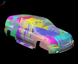
Laser scanner output creates a three-dimensional model of a surface, which due to its high density (often millions of points) is called a "point cloud" or "cloud of points". Shows a large point cloud set representing an entire vehicle. The different colors represent different individual scanning passes on the part.
Target inspection and validation
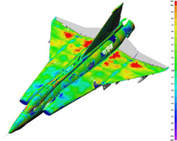
The 3D point cloud created by the 7 axis Absolute Arm combined with PC-DMIS can be used for dimensional inspection or GD&T, and the results compared againt nominal CAD values. With Cloud-to-CAD comparison, large point clouds can be overlaid on the CAD model for fast visual inspection of deviations (sometimes called a "weathermap" or "color map" see. Laser scanning can also be used for traditional (non-CAD) inspection using feature construction and dimensioning.Example inspection and validation applications:
- Verifying a part meets CAD, for incoming inspection, in-process inspection or final validation
- Verify Tool & Die dimensions to determine wear, evaluate repair or check modifications
- First article inspection
- Contour measurement, comparing parts to corresponding CAD models, 2D cross-sections or 3D topographical mapping.
- Production line or assembly process fine tuning
- Inspection of the mating of two parts.
Reverse engineering
Reverse Engineering is the process of taking a physical part, measuring it to determine its characteristics and the processing the data to creating a CAD model. This is often used in cases where the product design process has significant manual operation, such automotive design. Despite the advances in CAD, many designs still start life as a physical model which then needs to be turned into electronic form.Point clouds generated by laser scanning are processed in various ways to make them ready for conversion to CAD. Reverse Engineering software such as PC-DMIS Reshaper is used to create or import the scanned point cloud, manipulate, mathematically smooth and combine the scanned data so a representative surface model can be created.
Example reverse engineering applications:
- Create a 3D model for further CAD design or adaptation.
- Characterization of a mating surface so that another piece can be connected or joined to it.
- Create a "legacy" or "golden" part where no CAD or part drawing exists.
- Create an "as-built" model of a tool so wear over time can be compared
- Competitive part/product analysis
- Archival or historical preservation of artifacts to create a 3D record or copy.
- Copy/Scaling Milling and Rapid Prototyping
Example applications:
- Historical or cultural heritage preservation where artifacts are scanned to observe wear or deterioration
- Rapid prototyping of handmade models
- Rescaling of a physical scanned model
- Scanning of models for electronic purposes such as movies and videogames
- Ask us about our Laser Scanning Solutions.
How fast is the scanning?
Scanning speed depends significantly on the probe and the probe's field of view. On laser probes in general, you will be able to see the points collected "on screen" in real time. Sometimes this is referred to as "painting the part". Making scans at different angles to ensure all the relevant geometry is captured often results in a point cloud such as the one captured of the Liberty Bell, where it looks like someone went crazy with the spray paint.
Also significant to the overall speed is the scanner's number of points per second capability, the scanning path width, and the the density of points per line. The animation below compares the difference between a two different scanners, one with a narrow stripe and one with a wide stripe, capturing a 1 meter square flat plate at a mid field of view. The scanner with a wider (105mm) line width at mid-field of view, captures the surface in just under 3 minutes, where the scanner with the narrower line width would take over 13 minutes for the same part.
The application can be a contributing factor to scanner choice. Applications where speed and coverage are extremely important, but fine details are not, may require a scanner with a higher speed. Other applications with smaller, more complex parts, may work better with a smaller stripe width. Some scanners, such as the HP-L-20.8 allows the user to select a stripe width that best matches the application.
| Scanner with narrow scan width | Scanner with wide scan width |
| 44mm line width at mid field of view | 105 mm line width at mid field of view |
| 23 passses to paint plate | 10 passes to paint plate |
| 1mm line spacing, 13min, 2sec | 1mm line spacing, 2min 50sec |
Are more points better?
This depends in part on what you intend to use the data for. Surfaces that are extremely complex with lots of curvature will benefit from higher density scanning. Flatter surfaces, not as much. Feature extraction of characteristics such as holes, slots, cylinders and other prismatic shapes and also edges will benefit from higher density data as well. Consider the two images below, which are identical scans of a 15mm hole. The scan on the left was created with a low-density scanning probe, the one on the right with a top-of-the-line V5 probe. The extraction of and form measurement of the hole on the right will tend to be more accurate with the higher density data. Higher density data will capture textures more effectively, if this is important to you.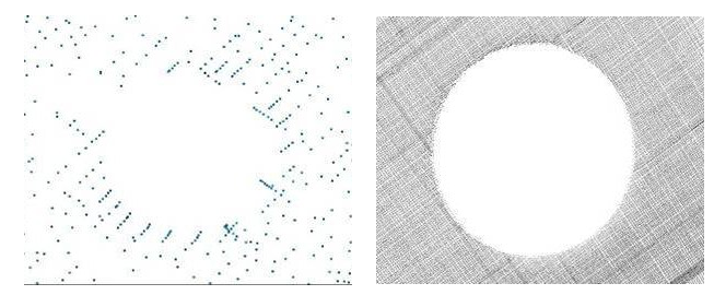
Does ambient light affect the sensor?
Many times, various types of lighting in a lab, studio, and factory environments can have an adverse effect on an optical device. While some types of scanning devices must have a light-controlled environment, this is not the case for probes used on ROMER arms. ROMER arms equipped with laser scanners employ a variety to techniques to overcome the effects of ambient light including optical filters, and exposure controls which are designed to ignore wavelengths of light except those near the laser being used. The net effect is that light from incandescent, mercury vapor, halogen and other popular lighting systems are rejected and do not affect the sensor.
Do surface conditions affect the laser sensor?
Traditionally measurement accuracy was affected by surface finishes. Highly polished chrome and shiny black surfaces were the most difficult to scan. Multi-colored surfaces or surfaces that transition in reflectivity can also cause problems for many scanners. ROMER arms equipped with laser scanners employ tools to cope with these situations, allowing most surface finishes and colors to be scanned successfully. Our premium HP-L-20.8 sensor employs automatic exposure control and flying dot technology to allow it to adjust automatically in real time to changes in material color and reflectivity, making it easy to scan nearly anything successfully. In the picture on the right, a part with three different colors and surface finishes and differing levels of reflectivity is easily scanned with the HP-L-20.8.
Do you have to powder the parts?
In all but the most transparent surfaces, the answer is no. Surface preparation by spraying with a powder (to reduce reflectivity and create a uniform surface) is undesirable for many reasons, ranging from the extra time it takes to prepare the surface, to the addition of measurement variability from the powder itself (studies show this can be up to 100 microns/.004" of measurement variability). While it was often the case that parts needed to be powered in the past, this is no longer the case.
Do temperature and environment affect the sensor?
Typical plant and machine shop environments are acceptable to the operation of ROMER arms with laser scanners. The sensors are not suitable for direct water or oil spray environments as it can adhere to the laser and camera lenses. The temperature should typically be between 15 and 35 °C and the humidity between 0 and 90% non-condensing. Environments where dirt, oil or other contaminants are present that can adhere to the sensor should be avoided, as this can influence measuring performance. These sensors are capable of reliable operation 24/7 in plant environments for many years.
Filtered vs. Unfiltered data... What's the difference, really?
Filtered data is sensor data that has been "filtered" or "processed" as the point cloud is being generated. This is typically performed by the 3rd party software packages as the sensor data is being read in to the software The raw sensor data is compromised because it's being filtered "while captured" and thereby data quality is an unknown entity.Unfiltered data is sensor data in it’s raw state, including all the outlier data, regardless of its cause. The original data can be evaluated independently. Using unfiltered data provides the true capability of the sensors' ability to accurately scan; to compare true data to nominal (print or CAD) data.
The ability to capture raw, unfiltered scan data independent of any 3rd party software is preferable, simply because it allows you to decide what you do and do not want to include in your data set. Often, the outlier data is cased by poor scanner performance, so the better your scanner is able to capture the true surface and not be "fooled" by external factors such as lighting, color and surface reflectivity, the more confidence you have in the results. Most point cloud packages or inspection packages have tools to remove or ignore outlier data at your discretion.
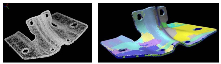
When I scan a part, do I get a CAD model when I'm done?
This is perhaps the most widely misunderstood aspect of laser scanning. The arm and scanner capture the geometry of the part in a 3D point cloud format. This is simply a file of the points in relation to one another, it is not a CAD file. To get a CAD file, you need to first create some sort of polygon based model from the point clouds, and then work to characterize the surfaces and features as a CAD model, often in a CAD system. These are offline processes which take place once the scan data collection is complete, and is actually the most time-consuming part of working with the 3D scan data. The image on the left is point cloud, again, showing the various scanned areas as different colored patches, the model on the right is the same data converted into a polygon mesh model, just the first step toward a full CAD conversion.