Optimising gearbox mechanisms: The role of tolerance ranges in high-performance sports cars
By Joel Ortis, Concept Engineer and Juan Lopezdealda, Sr. Manager Reseller Development, Hexagon’s Manufacturing Intelligence division

Engineering Reality 2024 volume 1
Accelerate Smart Manufacturing
Gearbox mechanisms control the quality and effectiveness of gear shifting. This impacts the vehicle’s speed, acceleration and fuel efficiency, which significantly affects vehicle performance.
Using specialised tools to test different tolerance ranges can help improve the vehicle’s responsiveness and reduce overall manufacturing cost.
Analysing the impact of design variables on assembled responses
Load tolerance ranges on components come from design specification; nevertheless, when the components are assembled in a mechanism for a specific actuation, accuracy is critical as they might have relative motions along the kinematic chain, resulting in unexpected displacements (higher or lower).
“Using this analysis strategy, the team quickly identified potential failures and adjusted tolerance ranges accordingly. This improved the mechanism’s response, enabling modifications to reduce the overall manufacturing cost.”
The expected motion accuracy requirement in that mechanism depends on how precise each component is manufactured, including a normal variation within the manufacturing process.
The assemblies have different responses; therefore, it is important to know the influence of each design variable to modify them according to the proper system function, and by doing that, we can always ensure a proper function of each assembled mechanism.
Optimising component interaction in gearbox control systems
We used a virtual prototype to identify the sensitivity of tolerance ranges on a series of components. The components in question were a chain of kinematic pairs for a motion mechanism designed to be part of a gearbox control system.
The smooth, precise motion of the control mechanism and the shifting gear speed of the gearbox are important when it comes to increasing the quality of high-performance sports cars.
Figure 1 shows two components. The yellow component leads the blue component towards a precise location to obtain the gear speed position. The resulting motion is due to the sub-assembly of the shifting control system, which is a kinematic chain of nine components with relative motion between them.
Ideally, when shifting from seventh to sixth gear, the blue component should follow the intended trajectory.
If the blue component is pushing over the tip of the guide, the driver can continue the motion toward the sixth gear. This phenomenon is named “partial block out.”
But if the driver cannot move the shift lever from seventh to sixth gear, this is known as “total block out.” This is the worst outcome. To complete the shifting, the driver must apply a slightly backward motion to prevent the yellow component from blocking the blue component.
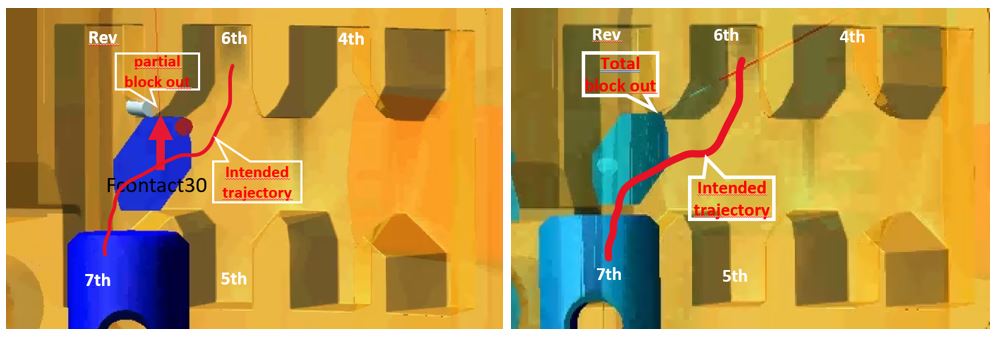
Figure 1. Partial and total block out and Intended trajectory.
Strategic mechanism analysis: Enhancing functional responses through Adams and ODYSSEE CAE
Proper design consideration that results in the correct tolerance ranges on components of the kinematic chain is critical for ensuring the motion does not result in total block out.
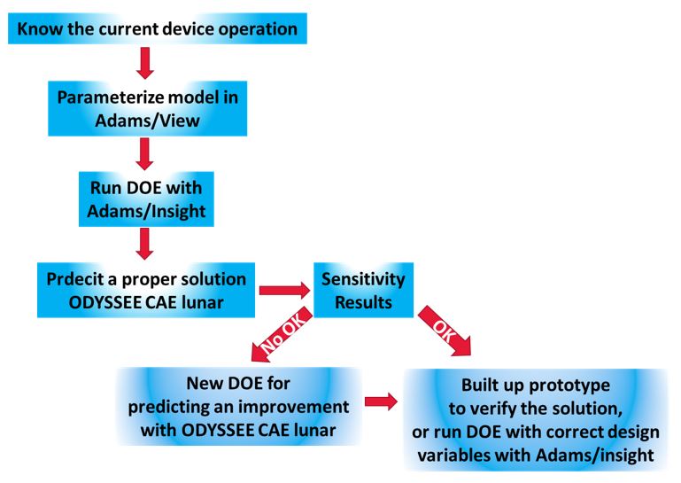
Figure 2. General analysis procedure
Adams software allows us to review the behaviour of mechanisms, define design objectives and run previous Design of Experiments (DOE) studies using Adams/Insight. This generates a data matrix that can be used as inputs into ODYSSEE CAE Lunar. This software can be used to learn from the data and predict new results for new design variables according to the design specification.
Additionally, new variable ranges can be assigned at the last analytical stage of the system if they are included in the previous ranges selected in the Adams/Insight analysis. Once the sensitivity results from ODYSSEE CAE are implemented, a new DOE with new variable ranges can be created to obtain a better functional response solution at a lower cost.
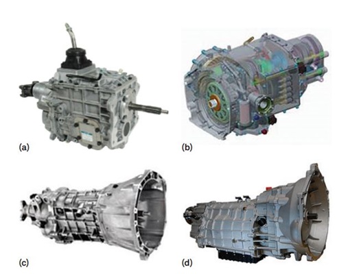
Figure 3. Transmission (a) full view (b) inner structures (c) actual part (d) outer surface.
Finally, this process can be repeated to create new prototypes and DOEs within Adams, covering a wider design variable range and building new DOEs.
The tolerance ranges of every mechanism in motion are defined with precision. Tolerance ranges are carefully defined for all moving mechanisms. However, even if two components interact perfectly in isolation, their combined effect in a kinematic chain with multiple pairs can accumulate and alter the overall motion and functionality, causing major or minor linear or angular displacements.
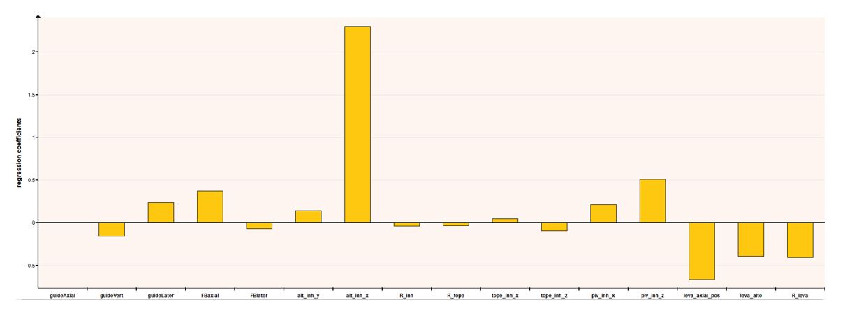 Figure 4. Sensitivity results
Comprehensive tolerance variations: Optimising the integrity of kinematic chains
A specific case study of the mechanism was analysed to determine the effect of tolerance ranges when the individual effect is accumulated along the kinematic chain, according to the procedure shown in Figure 2
The first simulation with Adams/View showed the functionality with every component in nominal dimensions.
The second simulation, which included the tolerance ranges in a DOE using Adams/Insight, was implemented to identify responses along the tolerance ranges of each of the components of the mechanism. The results revealed some malfunction cases.
These results were used as input data to ODYSSEE CAE lunar software to show the response for a combination of the design variables. They showed the sensitivity results for every tolerance range or design variable (Fig. 4).
It was possible to create a new DOE in ODYSSEE CAE using these sensitivity results. Three tolerance ranges were reduced by 40%, five were increased by 33% and four were doubled.
These changes resulted in an 8% reduction of partial block out compared to the original design.
These tolerance changes also reduce the manufacturing cost. In this case, five tolerance ranges were increased by 33%, and four tolerance ranges were increased by 100%. The iteration time for this new analysis took less than two minutes, in contrast to the iteration time with Adams/Insight, which took around “10 solving hours.” The first iteration provided the results as input data to ODYSSEE CAE, which used it to learn the mechanism behaviour according to each tolerance range.
This made it possible to predict the response of new tolerance ranges, which were defined in a new DOE within ODYSSEE according to the sensitivity results. Some of the tolerance ranges increased in value, showing that they had little influence on the responses. Others decreased in value, showing that they had some influence on the responses.
Reaching optimal functionality and reducing manufacturing cost
The team reached a solution quickly, allowing them to quickly iterate through different case studies by changing the tolerance ranges.
Using this analysis strategy made it possible to reduce the manufacturing cost. This is because the team only increased the tolerance ranges if they had minimal influence on the response.
The team only reduced the tolerance ranges involved in the response, affecting the mechanism functionality. This allowed them to define an optimal mechanism for optimal functionality at a low cost.