Hexagon Smart Assembly Shop: Connecting the physical and manufacturing virtual world
By Jeff Robertson and Dr Ingo Hahn, Hexagon’s Manufacturing Intelligence division
Engineering Reality 2024 volume 1
Accelerate Smart Manufacturing
Auto OEMs and suppliers are under continuous pressure to reduce product development, launch costs and time. There is an emergence of technologies as part of the Industry 4.0 transformation that can enable fundamental changes in the basic approach used to prototype and launch vehicles. This concept of the digital twin of the manufacturing process is what Hexagon calls the Smart Assembly Shop (SAS).
Through the integration of multiple solutions, including scanning and metrology, CAD morphing, gravity compensation, multi-physics process simulation and quality data management, Hexagon has assembled a platform that enables engineering teams to evaluate in detail the aggregate effects of the manufacturing process and take steps to mitigate issues before the first tool is cut as well as after non-conformance is observed.
Introduction
Every auto body and chassis structure is produced to tight dimensional specifications. Key features must be correctly located to align with other components in the assembly or to pass the consumer’s visual inspection, commonly called “flush and gap.” Over the last 100+ years, the traditional methodology has been to stamp or otherwise produce each individual (detail) component as close as possible to nominal. Various stampings, castings, and extrusions would then be joined into sub-assemblies using spot welding or other joining techniques — again attempting to hold nominal.
This process would repeat, station after station, sub-assemblies being married together, until there was finally a completed assembly — or, in the most complex example, a complete body in white assembly. However, the challenge with this approach is that each as-stamped component is a bit out of nominal, and each step in the assembly process contributes further to the dimensional variation.
Further, achieving individual detail component conformance does not guarantee that the assembly will meet specifications. Station by station, the dimensional variation from nominal evolves, and the root causes of variation become more and more difficult to identify. There is also the effect of process variation at each manufacturing stage that must be considered. While this effect has long been known and visualised, there simply was not a solution that adequately addressed the complex nature of the problem. Engineers instead relied on intuition, tribal knowledge, and trial and error to achieve their desired outcomes.
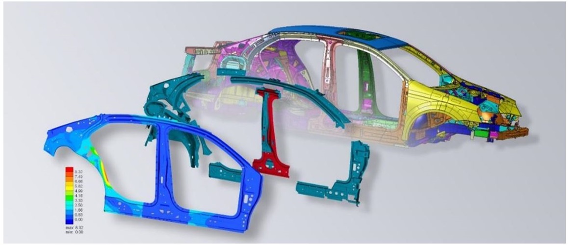
Figure 1. Breakout assembly of welded auto body side.
To significantly reduce cost and time in the product development and launch process, we must minimise the number of physical prototypes and iterations required to achieve dimensional conformance of the final assembly, as well as the quantity and complexity of fixturing. Two basic disciplines of the SAS solution are described here: Virtual Check Fixture (VCF) and Virtual Assembly (VA).
Smart Assembly Shop — Virtual Assembly
The Virtual Assembly process is a similar workflow that leverages many of the same systems and principles as the Virtual Check Fixture. The SAS Virtual Assembly workflow focuses on the steps to physically fixture, clamp and join multiple individual components and sub-assemblies together into successively larger assemblies as the assembly process moves down the line. The objective is to predict the assembly process’s behaviour through multi-physics clamping, welding, and joining process simulations while considering the realities of dimensionally non-nominal components entering the workflow.
The outcome of the Virtual Assembly process is an efficient assessment of the manufacturing process that enables engineers to quickly evaluate resulting assembly behaviour much earlier in the product development cycle. By digitising the Virtual Assembly workflow, several benefits can be gained:
- Reduce calendar days for new product development and launch
- Reduce and potentially eliminate the cost and effort required by physical prototyping
- Improve the degree of confidence in the design and manufacturing process earlier in the product development cycle
- Ability to identify required design and process changes earlier in the product development cycle
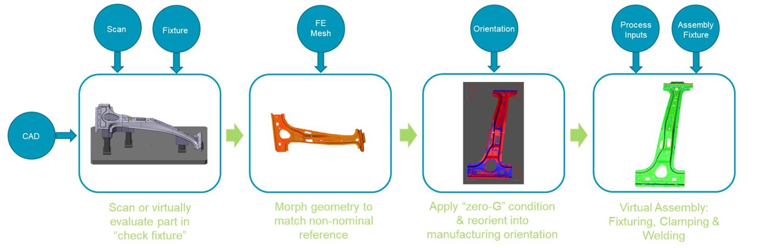 Figure 2: Virtual Check Fixture Workflow
An example of a Virtual Assembly workflow is depicted in Figure 3. In this case, it starts with multiple non-nominal geometries entering the workflow, including components/fixturing, metrology schema, and process data flowing from the CAD/PLM/enterprise software systems into the platform. That data generates a digital version of the physical assembly process. The virtual process must mirror the physical process as closely as possible.
The geometric representation of the components can be based on nominal geometry directly from CAD. It can also leverage metrology scan data (STL) to perform geometry morphing as described above to obtain non-nominal geometry representations in the virtual assembly models. The Virtual Assembly process simulation module then runs a discrete process simulation for each stage of the manufacturing process, which may include metal forming, trimming, adhesive application, clamping, mechanical joining, welding, hemming, etc.
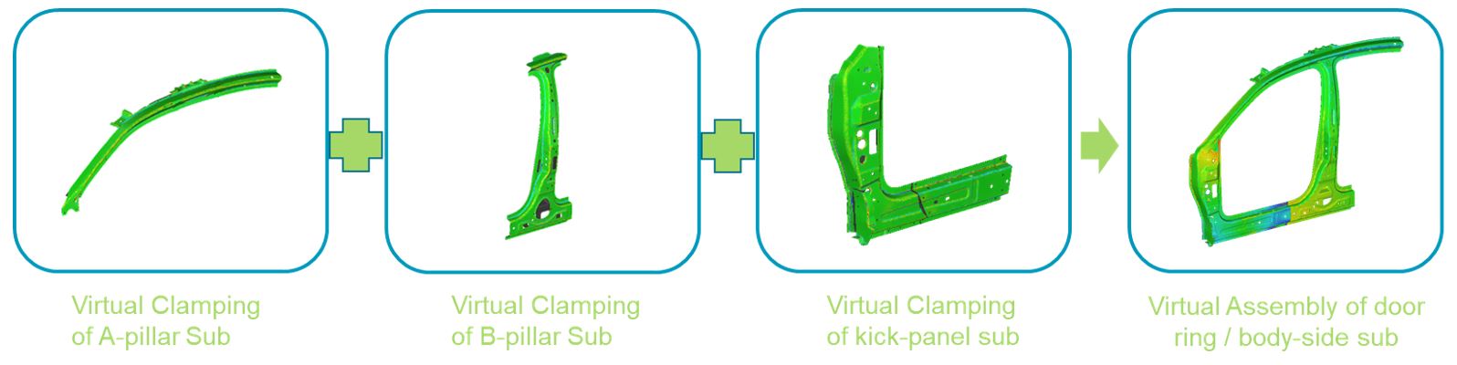
Figure 3: Virtual Assembly Workflow
Results from each stage are successively brought together into subsequent stages, to be joined into ever larger assemblies. After each assembly stage, the simulation results are evaluated by applying a metrology schema such as the Reference Point System (RPS), just as it will be applied during production. Based on these results, the engineering team can take steps to improve/optimise the process by various means, including but not limited to modifying the clamping and fixturing approach, modifying the welding/assembly process, modifying the weld sequence, modifying previous station configurations or modifying individual component geometries.
Flexible by-design
The Virtual Check Fixture and Virtual Assembly workflows are designed to be flexible. The solution is developed with a host of different use cases in mind. It is up to the user and their team to decide how they want to utilise the software by selecting templatised workflows that simplify the selection and setup. Figure 4 illustrates different selections a user may make to define the desired process setup.
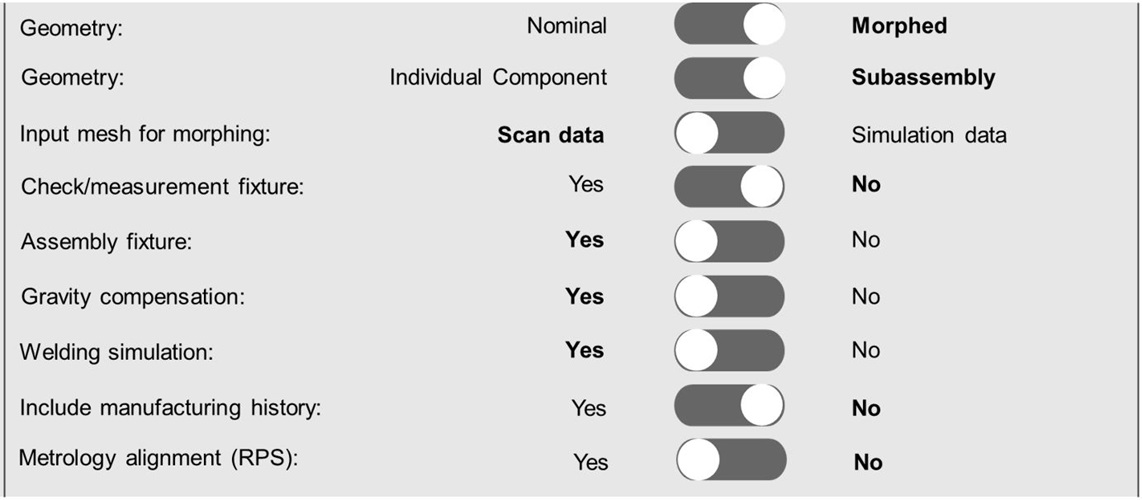
Figure 4: SAS Inputs
There are many potential use cases that SAS users can complete with the solution. Below are a few example use cases/studies identified by our customers:
- Evaluate interaction between design and manufacturing process: How does the combination of clamps, fixtures, weld locations, weld sequence, etc., impact the macro deformation of the assembly?
- Understand the impact of non-nominal geometries in the process: How does the process behave differently when the part or sub-assembly geometries deviate from nominal?
- Perform virtual check-fixture of parts and sub-assemblies: How do non-nominal parts and sub-assemblies fit up into the check fixture individually and with other parts?
- Perform fixture robustness/stability evaluation: How repeatable is the process of clamping parts into the fixture? Will the part settle in the same location every time?
- Perform virtual metrology to understand the impact on dimensional tolerance: What is the impact of the studies described above concerning the metrology or dimensional control plan?
Metrology-enhanced simulation solution
Combining metrology hardware, software, process simulation, and quality data management into a cohesive, purpose-built solution affords engineers a streamlined workflow that makes this advanced analysis efficient and effective in a production environment. An integrated solution links together several individual technologies to support the Smart Assembly Shop process. It manages the data through the various steps in the process, enabling efficient handling of large quantities of scan data, metrology data, assembly information, and simulation results. The platform can do this for many components through the various steps in the workflow. As a result, engineers can quickly analyse data and interpret results instead of spending time trying to get the software to work.
Using an integrated solution, engineers can efficiently deduce the drivers of undesirable behaviours and identify the optimal approach to mitigate them. Scripted software interfaces can drive the large-scale automated design of experiments (DoE) and optimisation, thus enabling engineers to evaluate many potential combinations of clamping, fixturing, welding sequence, and many other geometry and process inputs without human interaction. Finally, the integrated solution enables various stakeholders with different roles in the organisation to interact with virtual and physical quality data and to draw conclusions about drivers of dimensional quality.
Conclusion
Hexagon’s Smart Assembly Shop combines several advanced technologies in a way that can dramatically improve the way the industry performs product development and product launches. This solution will help to reduce design and manufacturing process development loops by evaluating the prototype process virtually. In this way, it will also significantly reduce the cost and calendar days required to take a design from inception to production-approved process.