Modern day Metrology surpasses trial and error
Accelerating inspection of tube and pipe dimensions
Contact us
Tube and pipe bending shops are a rare breed in the manufacturing industry and they face important challenges exclusive to their discipline. Measuring the very tubes and pipes they bend is one such challenge. In this industry, accuracy counts. A tube that does not meet specifications will likely head to the scrap bin, as it won’t have the proper clearance to mate-up and connect with subcomponents. Market forces demanding tighter tolerances and better costs are forcing tube and pipe benders to rethink their processes and improve accuracies as well. Advancements in measurement technology designed specifically for this application can increase productivity and precision while dramatically reducing scrap rates.
The traditional approach
The old school method of measuring tubes and pipes comes down to trial and error techniques that waste precious time and resources. In cases where CAD drawings are available, the bend radius is given. A plotter produces to-scale drawings showing the remaining specifications. Known in the industry as LRA (length, rotation and angle) or PTB (pull, twist, bend), the drawings must try to replicate in 2 dimensions what is happening in 3D space. When a tube is produced, it is placed on the drawings and visually inspected. Tubes that do not meet spec are rejected and the CNC bender is adjusted. When the adjusted tube is produced, it is brought back to the drawings and visually inspected as well. The process of adjusting the bender and inspecting the tube continues until it finally conforms to specification.
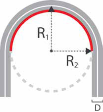 If CAD models are not available, as is often the case with reverse engineering applications, the centerline radius should be calculated. One method, as illustrated, is to measure the circumference of the bend by pressing a tape measure against its inner surface from where the bend begins to where it ends (the red area). The result is then multiplied by the number of times it would take to make a complete circle. In the simplified example, it is multiplied by 2 since the bend is 180° (multiply by 4 if the bend is 90°). The result will be the circumference or ‘C’. Working through R2=C/2 where is 3.14 yields ‘R2’ as the inner radius. Adding half of the tube’s diameter (D), gives the centerline radius. The easiest way to measure the rest of the tube, is to sketch its outline from various angles on cardboard. When a tube is produced, it’s placed on the cardboard and visually inspected. Then the iterative process of readjusting the CNC bender and remeasuring, as mentioned previously, takes place.
The modern approach
Modern technology is providing the tube bending industry with attractive and economical alternatives to the trial and error approach. With portable coordinate measuring machines (also known as articulating arms), tubes are inspected using the standard X,Y,Z point data used for measurement on traditional CMMs. Employing a single-vendor solution developed over the course of three decades specifically for tube measurement enhances inspection further. The ideal choice is ROMER’s Tube Inspection System which is developed, manufactured, and supported by Hexagon Metrology. The ROMER Tube Inspection System includes a portable CMM with patented absolute encoder technology and easy to operate zero-g counterbalance, non-contact tube probes, Data Overlay Camera System (DOCS) software, and an optional CNC bender interface - all the tools needed to quickly and accurately measure tubes and pipes. An additional benefit is the system’s ability to measure other geometric features attached to tube components such as brackets, flanges, or bosses by allowing the operator to rapidly switch between contact and non-contact probes without the need for recalibration.
Although the initial purchase of ROMER’s Tube Inspection System will have financial implications, there are several ways a tube bending shop can keep costs in line. For example, an entry level arm provides more than adequate accuracy for the majority of tube inspection applications. With regards to the probes, the cost of non-contact tube probes is substantially lower than more expensive laser scanning sensors. Also, since tube bending shops are able to buy only the tube probes that are needed, they do not run the risk of wasting money on technology which will not be utilized to its full potential. All of these factors contribute to a lower initial purchase price when compared with similar systems on the market.
To measure a tube using this system, it must be securely mounted. This is especially important for thin walled, small diameter tubes as they may deflect if placed on a table. A tube probe is then passed over the tube at each point of bend change in sequence from one end to the other. The probe’s visual guidance, via a red laser stripe, indicates where points have been taken while the infrared sensor ‘sees’ and locates them on the X,Y, and Z axes. The DOCS software platform automatically computes the geometries of the tube based on the point locations in 3D space. Once this information is collected, the software compares actual data with nominal data and calculates the corrections. These corrections are either manually input into the bender or directly uploaded using an optional software module. The next tube produced automatically meets specification.
Reverse engineering applications are also simplified using the tube inspection system. By measuring two neighboring straights and then sweeping the bend with a tube probe, DOCS calculates the bend radius as well as the LRA data. The information is then programmed into the CNC bender to produce a virtually identical tube. For tube bending shops which prefer to use a laser scanner in some of their reverse engineering applications, use of a non-contact tube probe for tubes and a laser scanner for other inspection tasks is possible.
Manual meets modern
One of the issues with manually inspecting tube and pipe is the inaccuracy inherent with visual measurements. A tube may appear to meet tolerances, when in fact it does not. If such a tube passes inspection, it may ultimately be rejected by the customer. Tolerances smaller than what the human eye perceives are easily measured with the tube inspection system and corrections can be made before product ships. Accuracy is greatly improved with the ROMER Tube Inspection System and, depending on the length of the arm, can be as tight as ± 0.0009” (0.023 mm).Modern measurement technology reduces the time and resources required to get tubes to meet specification. Using conventional methods, time is wasted readjusting, remeasuring, and readjusting again. It is not unheard of for this process to take most of the day. Also, while making adjustments, every tube is scrapped. If set-ups last most of the day, an entire scrap bin could potentially be filled by the time an accurate tube is produced. ROMER’s Tube Inspection System reduces inspection time to minutes instead of hours. It also significantly reduces scrap since its first readjusted tube conforms to specification.
Tube and pipe bending shops employing the latest CNC software and hardware could better leverage this asset with a portable CMM providing on-demand inspection. Considering the amount of time, energy, and scrap saved, it’s an investment that merits serious consideration. Tube and pipe bending shops may be a rare breed, but they deserve customized inspection solutions to make life easier.