Automated CT quality inspection for tooling springs saves time and resources
by Kamil David Szepanski, Head of Technological Development and Product Development CT&AM, F. & G. Hachtel GmbH & Co

Engineering Reality 2023 volume 2 edition
Empowering Makers for an autonomous sustainable future


Figure 1. Injection moulding die.
In additive manufacturing, they’ve chosen the hot lithography process, which allows them to achieve excellent material properties and surface structures. In addition, they can produce injection moulding components with the highest precision.
Their plastics specialists cover the entire process chain of plastics processing. The experience gained from their tool and mould making and a large plastic injection moulding production enables them to solve problems faster.
Perfection isn’t an option
In competitive mould-making and injection-moulding markets, where tight pricing and narrow profit margins are the norms, end quality is the one thing that distinguishes a manufacturer from its competitors. Moulds must be perfect, and the correct-specification parts made from them must be delivered on time and with no production delays. It might seem simple, but genuinely understanding all sources of underlying part variation is not. Managing variation, however, will always save time and money and boost customer confidence.
Lessons to pass along
Hachtel operates a multi-service bureau for injection-moulding, mould-making, CT, and Additive Manufacturing. The injection-moulding branch specialises in complicated processes and multi-component parts and materials. Tooling automation is important because the assembling tools put together the part directly as it leaves the mould. Our customers are primarily in the appliances, electronics, and automotive industries. Exacting part qualification is demanded and achieved with the help of CT software analysis.
Other manufacturers facing similar customer demands and challenges may benefit from a supplier situation we encountered that allowed us to test our inspection solutions thoroughly.
Taming of the spring
Recently, we received a large batch of defective tooling springs. Our inspection system, which relies on software from Volume Graphics, identified the problem immediately. Because the software can automate inspection, the team decided that, rather than reject the entire shipment; it would be better—and a test—to use the software’s Adaptive Measurement Template function to identify and save any good parts that might remain in the production lot.
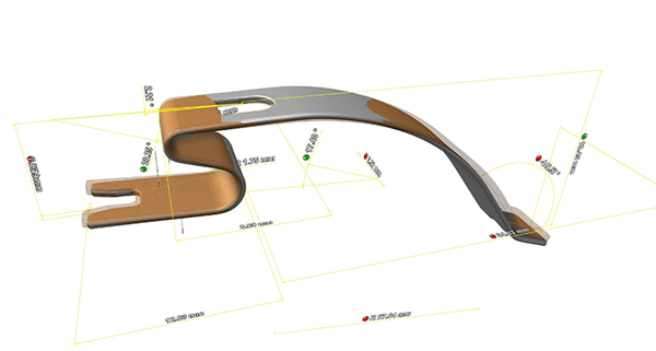
Figure 2. Spring overlaid with nominal CAD model and measurement features.
The springs are inlays for an injection-moulding process and receive a plastic tip on one end. Because Hachtel gets hundreds of thousands of these springs, its tool-production process, by necessity, is highly automated. A positioning system places each spring individually on a transfer plate. From there, a handling arm loads a set of springs into the moulding tool.
To reduce the rate of potentially expensive, periodic downtimes, the company decided to control all the springs upon arrival and to use an inspection to determine whether they get rejected or will work and can be processed. Receiving a shipment of mostly deformed springs put the CT inspection software and related handling functions to a “stress test,” one the company felt it could benefit from if further studied.
Normal CT inspection typically uses a classic 3D design with defined dimensions as a basis for comparison. However, routine springs rarely match the original CAD model perfectly, and spring shapes can fluctuate between batches. These fluctuations made managing the first set-up transfer of measurement templates from the CAD and even from proper pre-existing springs complicated and time-consuming.
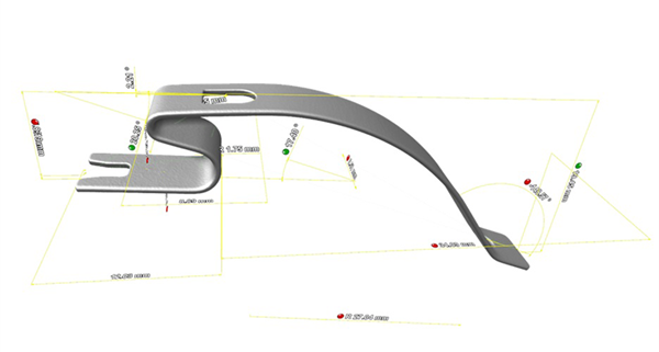
Figure 3. Spring with measurement features depicted.
However, with the fully automated Adaptive Measurement Template, we could ignore a pre-alignment step and didn’t have to perform any refitting of geometry elements. Indeed, after applying the measurement template, we could take target features and geometries and create a “registration” of accurate part shapes. The registration—based on a saved datum system that included the distortion of the parts—was covered within the transfer. This coverage allowed for slimmer and less complex measurement templates.
Time and resource savings
The entire non-automated CT inspection process per spring was previously a two-minute preparation stage. The pre-alignment calculation took another three minutes, copying the measurement template took only 15 seconds, and the manual refit of the elements took another five minutes. The classic approach meant 10 minutes per part, of which the second half was manual work with unnecessary labour costs.
When using the automated adaptive measurement template, the process still consists of two minutes of preparation, and the template transfer takes about five minutes per part. All in all, this saves approximately three minutes per sample. The benefit, however, exceeds this three-minute time saving because the process runs automatically and doesn’t require further attention or adjustments. So for tooling and production shops, this methodology effectively allows for the entire automation of measurement tasks, some that previously needed to be performed manually.
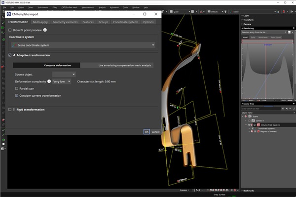
Figure 4. VGSTUDIO MAX software screenshot showing adaptive measurement template.