What is reverse engineering?
Reverse engineering is useful to analyze product functionality, analyze subcomponents, estimate costs, and identify potential patent infringement.
Contact us
Reverse engineering is useful to analyze product functionality, analyze subcomponents, estimate costs, and identify potential patent infringement. It may also be used to supply documentation that was either lost or never written, typically for parts designed before CAD software became widespread.
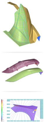
The physical object can be measured using 3D scanning technologies mounted on coordinate measuring machines (CMMs), portable coordinate measuring machines (PCMMs) such as arms, and structured white light digitizers. The measured data, usually represented as a point cloud, lacks topological information and is therefore often processed into a triangular-faced mesh (STL) file and then modeled into a more usable format such as a set of NURBS* surfaces or a solid CAD model.
* Non-uniform rational basis spline (NURBS)
Small and large companies alike use reverse engineering to bring existing physical geometry into a digital environment. Some examples of reverse engineering applications include:
Automotive industry
- Design sheet metal die tools that were hand worked and have no digital record.
- Digitize hand-made clay models at design studios.

Aerospace industry
- Provide digital data on as-built components for assembly processes.
- Archive legacy aircraft components (such as 747 parts made without CAD).
- Recreate full sized aircraft for FEA analysis by the FAA.
Architecture & artwork
Create one-of-a-kind, hand-made designs digitized for construction.
To create a fully parametric model, an advanced CAD package (e.g., Catia, Solidworks, etc.) is typically used to get the final deliverable. There are inherent losses in fidelity that occur during the Reverse Engineering process from the following:
Measurement hardware – all measurement systems contain an uncertainty in the volumetric accuracy due to system noise or the environment. One of the side effects may be loss of sharp edge detail.
Converting the point cloud to a mesh - data smoothing and decimation have to be taken into account.
Wrapping a NURBS surface to the mesh - fitting errors and curve continuity are considerations.
For an organization that is uncertain of their Reverse Engineering needs, Hexagon Metrology provides consulting services as well as complete reverse engineering capabilities for those who are unwilling or unable to invest in them.
Once you've considered what you hope to achieve, and the inherent benefits and drawbacks, you must analyze the application. This analysis should include:
Part characteristics
Size
Small parts often have tight tolerances which typically exclude them from scanning technology. This is because noise level (and uncertainty) of this method usually exceeds the tolerance of the part. Probing or analog scanning with a CMM, and the appropriate probe tip size, is usually ideal in these circumstances.A good rule of thumb is to use a system that has 10X better uncertainty than is required for the final model. Unfortunately, it is rarely achievable.
Measurement of big parts with a CMM or PCMM can be slow, if not impossible, when dense scan data is required. ‘Leap frogging’ an arm (ie moving the PCMM around as the part is measured) can blow the tolerance budget unless a feature such as GridLOK is available. Leica T-Scan laser trackers and Cognitens white light scanners may be better choices for parts that are substantially larger than a ROMER arm’s length.
Tolerance
Prismatic machined features, such as planes and holes, or parts that require high accuracy (less than 25-microns per meter) should be contact probed on CMMs or PCMMs. The downside to scanning with probes is a longer data collection time and an increased risk of the part accidentally moving during measurement. Flexible parts and parts with complex contoured shapes should be measured with non-contact scanners when possible.Features
Relief patterns, cast holes, and edges are some of the features that need to be taken into account. Analog probing can measure small radii very accurately, but the process is slow. Laser scanners set to minimum point spacing can pick up fine details, but small features can get lost in the uncertainty noise.Line of sight
Probes can reach areas out of the line-of-sight of scanners. Laser scanners may have difficulty getting into tight areas due to head size and short stand-off. Most scanners can get data when the sensor is angled about 65-degrees from the surface normal.Once you've considered what you hope to achieve, and the inherent benefits and drawbacks, you must analyze the application. This analysis should include:
External factors
Vibration and environment
During the measurement process CMM and PCMM arms, scanners and trackers require that the part be immobile relative to the measurement hardware. This means the inspection environment must be stable.
Required density of data
Data density is related to the point spacing (resolution) and thus the fidelity of the measurement. This is often discussed in terms of surface tolerance, or the angular deviation between adjacent points. High density data is often required on features (holes, edge details, etc…) for extraction from point clouds.Required speed
A good rule of thumb when weighing the benefits of probe scanning versus laser or white light scanning is to consider both data collection and mesh processing speeds. Typically a probe will be slower to collect data but will allow it to be processed more quickly. Conversely, laser or white light scanners will allow rapid data collection, but will reduce the mesh processing speed.
Operator considerations
Ergonomics
Measuring a large part with a laser scanner can be exhausting due to the need to maintain ±1 inch stand-off to get a 3-inch swath per scan. White light scanners, such as WLS 400A, WLS 400M and WLS qFLASH (formerly known as Cognitens), help in this instance.Ease of use
Measuring points with a manual probe can get tedious if numerous points are required. Manually driven laser scanners generate non-uniform point clouds which can increase the time for mesh processing and production of the final model.
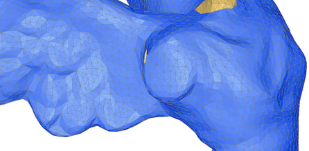
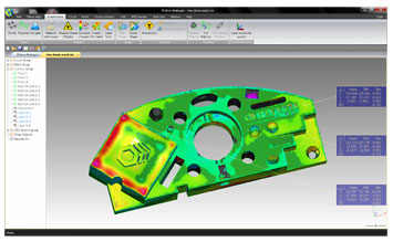
The reverse engineering compatible software, PC-DMIS Reshaper interprets the data measured (sometimes numbering in the tens of millions) and creates 3D point cloud meshing. Although the software is stand alone, it interfaces easily with 3rd party software such as Polyworks, Geomagic, and Rapidform.
Meshing in PC-DMIS Reshaper is incredibly fast. The key lies in the innovative triangulation algorithms developed by the PC-DMIS Reshaper This enables a more accurate triangulation process to be performed with fewer points which speeds up the process of meshing; often accomplished in mere seconds.
Once a mesh is created, it can be manipulated in the following ways:
- Refined with hole filling, smoothing, or deformation tools.
- Segment sections of the mesh.
- Compare the mesh to an IGES file for ‘weathermap’ style inspection.
- Export it as an IGES file.
- Export it as an STL file for rapid prototyping.
You deserve all the accuracy you can get! Inherently, the accuracy of a PCMM is not as good as a fixed CMM which should be a consideration. If a ROMER PCMM (arm) will not meet your needs, there are other Hexagon Metrology products to choose from.
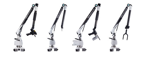
However, ROMER arms feature additional scanning capabilities that improve reverse engineering. The scanning options include:
HP-L-20.8 External Laser Scanner - A high-precision, non-contact laser scanner with the capability to distinguish between a variety of colors and surface finishes. The HP-L-20.8 features increased accuracy for tight tolerance applications.
Integrated RS2 Line Scanner – Standard on the ROMER SI systems, the RS2 collects 50,000 points per second and is calibrated at the factory to the arm.
For ROMER arms, the ideal part would be 1/3 to ½ the size of the measurement volume. Parts that have a bad line of sight, difficult for Leica laser trackers or WLS white light digitizers, could be measured using ROMER’s probe capability. Prismatic and contoured shaped parts would benefit from the scanning feature.
When measuring a part that is larger than the arm’s measurement volume, typically a ‘leap frog’ is required. ‘Leap frogging’ requires the arm to calibrate itself based on 3 arbitrary points on the part being measured. As the arm is moved around the part, the inherent measurement discrepancies which exist are compounded thereby decreasing overall measurement accuracy. ROMER’s patented LOK features, GridLok and TooLOK for example, eliminates the ‘stacking error’ associated with ‘leap frogging’.
Another feature ROMER arms have to offer is their ergonomic design. The ROMER arms are equipped with low profile, Zero-G counterbalances and patented SpinGrips which allow them to ‘float’ in the operator’s hands. This reduces stress on the arm thus maximizing accuracy and repeatability while minimizing user fatigue.