How to align a crankshaft on a CMM
Crankshafts for internal combustion engines can be a bit tricky to align on a coordinate measuring machine because they are mostly a series of cylinders.
Contact us
 Crankshafts for internal combustion engines can be a bit tricky to align on a coordinate measuring machine because they are mostly a series of cylinders. The technique described below shows how to align a crankshaft for CMM inspection on a machine such as a Global Advantage.
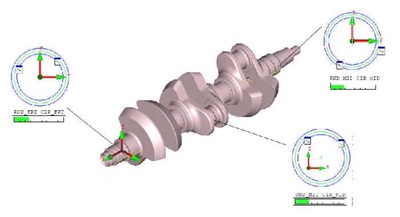
The crankshaft was fixtured nearly parallel to the CMM Y-axis (front to back). In this example one piston arm-mounting journal is the reference:
Level (spatial alignment) steps:
1. Front and end bearing journals are measured as circles, temporarily using the CMM workplane (ZX) or a measured end plane on the part.2. Construct a 3-D axis line between the circles.
3. Level the CMM axis to this 3-D line.
Rotation (planar alignment) steps:
1. Measure the top journal as a circle. Because we are already leveled, this time we can use the current ZX plane.2. Construct a line from the 3-D axis line to the circle.
3. Rotate +Z about +Y so that it is parallel (in the ZX plane) to the constructed line above.
Origin (translations) steps:
1. Set X=0 to the 3-D axis line that +Y is leveled to.2. Set Z=0 to the 3-D axis line that +Y is leveled to.
3. To set Y=0, a feature that locks the translation is needed. In this example, measure a plane on one of the shaft steps and create an intersect point between the 3-D axis line and the plane. Set Y=0 at this point.