Burning area extraction
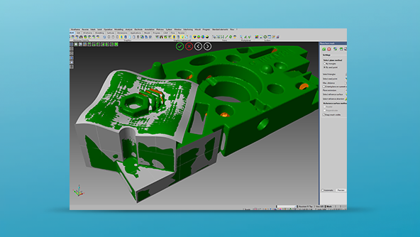
After identifying the areas which need to be manufactured with an electrode, enclosing the area with a 2D or 3D boundary provides a quick and simple way to arrive at the required electrode geometry. Graphical face selection is also available to permit easy extraction of the more complex areas. Understanding that VISI Electrode is a tool to compliment the experience of electrode designers, VISI combines automation with the ability to manually construct geometry and apply it to the electrode. This technology combination provides the user with the freedom to edit the design and ensures that it will always be possible to complete the electrode design.
Electrode creation
An intuitive interface guides the user through the creation of the electrode nose. Options are available for adding extension height with either vertical or tangential extension. For open-sided electrodes, multiple extrusion directions are available for side extension. At any point within the electrode creation process, dynamic animation and collision checking is available.
Blank, base and stock creation
The electrode base and stock are interactively added to the electrode. Electrode name, material, burning operation type, identification marks, edge chamfers, position and rotation can all be applied. Any information added is automatically carried through the electrode project to the final HTML report.
Holder creation
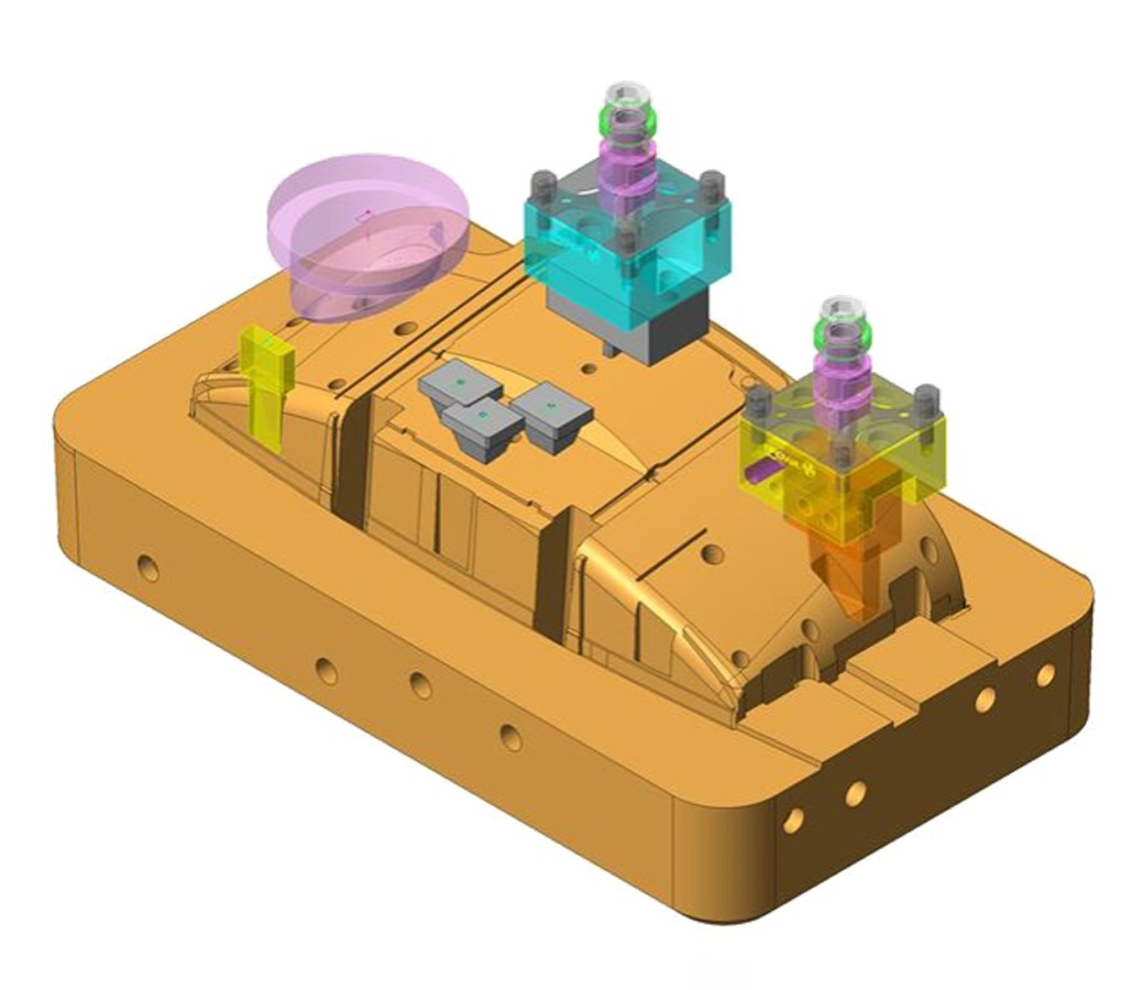
Holders can be constructed manually by applying width, depth or height, or simply selected from an extensive library. Where access for the electrode is limited by neighbouring surfaces, the holder can be offset from the center of the electrode to provide enough clearance for the EDM machine to operate. Dynamic animation and collision checking ensure that the complete electrode does not violate the part geometry.
Electrode management
The EDM manager provides the operator with a tool to manage the work piece, electrode, multiple electrode positions, vertical, horizontal and angled simulation, collision checking, HTML report and EPX output. To ensure compatibility with other CAD/CAM systems, each electrode can be automatically exported relative to the correct workplane using a neutral data format such as IGES, STEP or STL.


