Perfecting the last Hubble rendezvous
NASA Goddard- USA
Contact us

When NASA comes to mind, one instantly envisions their mission to launch vehicles to the moon and beyond. Yet the agency has a secondary mandate. Whatever NASA puts into low earth orbit must be safely brought home upon its expiration date.
With a life expectancy of 20 years, the scientific community speculated the Hubble Space Telescope would fail in the next few years without repairs. After years of deliberation and public outcry to save the beloved Hubble, NASA announced a fifth and final Shuttle-to Hubble mission. The seven-astronaut crew of Servicing Mission 4 will conduct the last restoration of the observatory in September 2008. Launched in 1990, the telescope has broadcast over 750,000 celestial images, and has been a major contributor to modern astronomy and space exploration.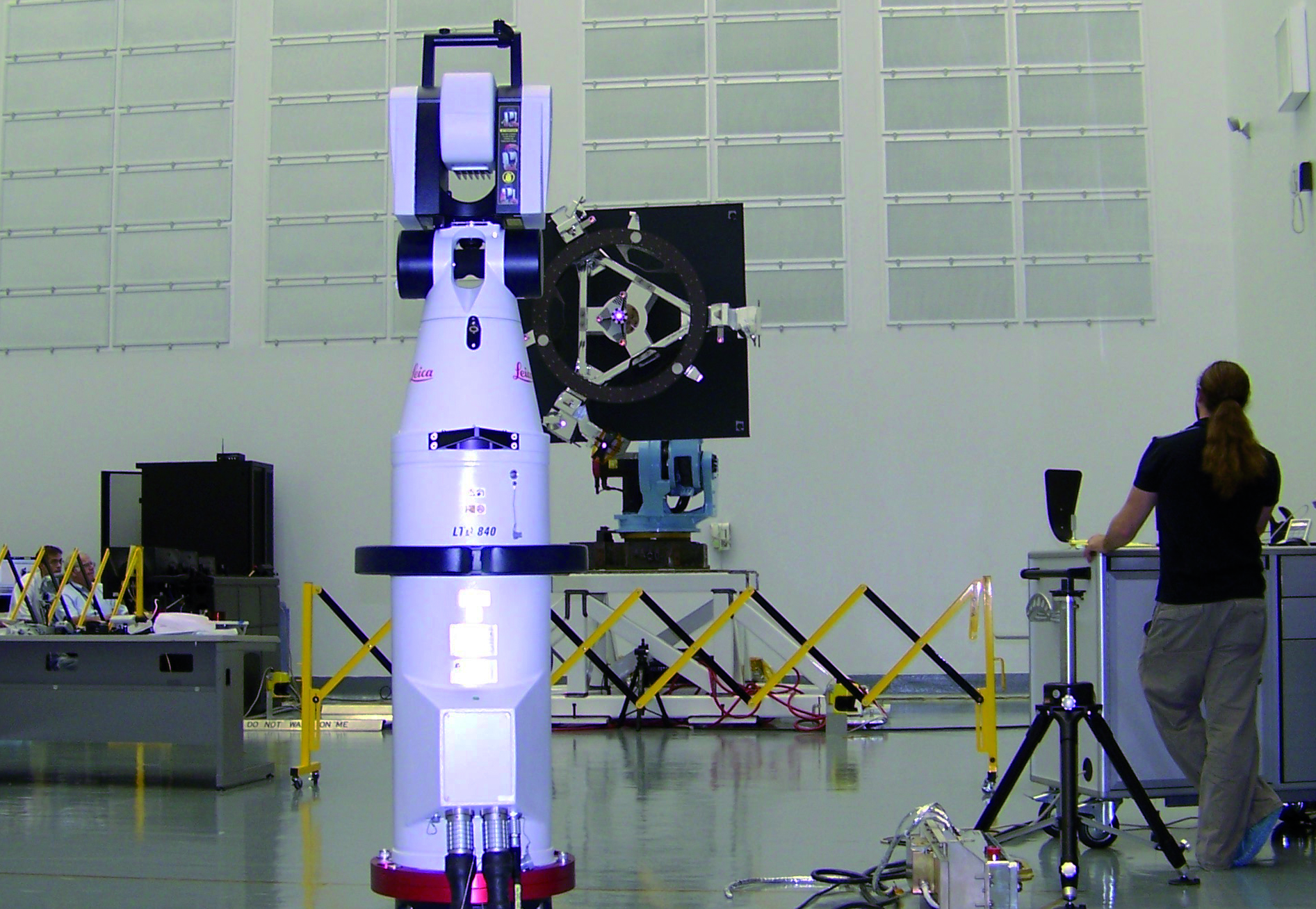 This extreme makeover will buy the space observatory more time…resetting its retirement to 2013.
Meanwhile, the telescope’s ultimate destiny is still being hashed out by NASA. Based on extensive analysis, the agency concludes the Hubble is unlikely to re-enter the earth’s atmosphere on its own before 2020. Preparations for the eventual de orbit of the telescope are under way at NASA Goddard Space Flight Center, in Greenbelt, Maryland. The Hubble resides 353 miles above the Earth’s surface, and interestingly enough, the 13-ton observatory does not have a propulsion system. NASA is devising a plan that will autonomously link up their new shuttle or other robotic vehicle with the telescope, add the necessary propelling force, and thrust it back toward Earth. Destination: an uninhabited stretch of the Pacific Ocean. While a de orbit module project for Hubble has been canceled, the quest for sensor technology and the creation of an attachment fixture has continued full speed ahead. The fixture will be outfitted to the end of the telescope during Servicing Mission 4.
Bo Naasz, NASA aerospace engineer at the flight dynamics analysis branch, led the week long endeavor. Naasz and other team members burned the midnight oil for several days in the simulated environment. Representatives from NASA, Fanuc, Leica Geosystems, Neptec, Ball Aerospace & Technologies Corp., and Advanced Optical Systems offered their expertise for the duration the exercise. On stage were 5 key components: robot, soft capture mechanism (also called an attachment fixture), crew exploration vehicle (CEV), space-certified sensor technology, and a laser tracker with a wireless probe.
At one end of the clean room, the attachment fixture was mounted onto a Fanuc robot, which moves the fixture in a floating spacereplicating motion. At the opposite end of the clean room was a full sized CEV mockup positioned on its side. Just inside vehicle’s opening were 3 different sensor systems used to locate the fixture and provide positioning data to align the CEV with the Hubble’s attachment fixture. And lastly, to the left of the CEV, was a Leica laser tracking system used for data redundancy feedback.
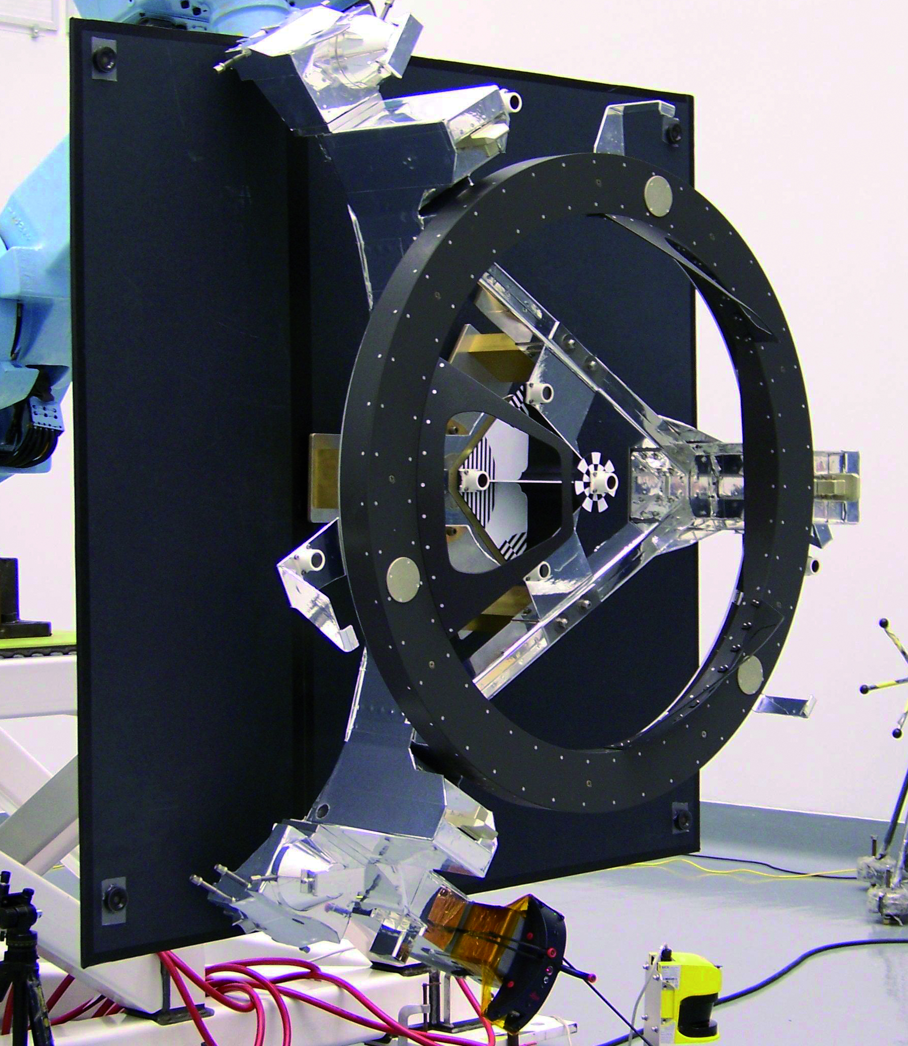
“The testing being done is laser imaging of the soft capture mechanism, which will be installed on Hubble during Servicing Mission 4,” states Bo Naasz. “The soft capture mechanism has retroreflectors and a LIDS adapter on it. LIDS is a low impact docking system. The objective of our work is to make the next rendezvous with the Hubble easier. In the past, our Hubble encounters were made with the Space Shuttle, and Servicing Mission 4 may be the last time we go back to the telescope with Shuttle. We believe a final rendezvous with the Hubble will occur, as NASA safety requirements necessitate that we park it somewhere in the south Pacific Ocean.
“In anticipation of this event, this week of testing was all about demonstrating our ability to estimate relative position and relative orientation with our suite of sensors to the soft capture mechanism. We mounted the soft capture mockup on the Fanuc robot, which provided a limited 6 DOF motion moving the target around while we are imaging it with engineering prototype relative navigation sensors. The Leica LTD840 was used to provide “truth information” for the relative positioning and orientation, so we can compare the truth data to the sensor data, and determine how well the sensors performed. We are trying to gain as much expertise as we can with these technologies and the target we will ultimately use for the last Hubble rendezvous.”
 The three sensing technologies being evaluated offer unique approaches to pose and position measurements, rendezvous and docking issues, and orbital proximity operations. Neptec’s TriDAR integrates a dual-sensor 3D scanner and a full pose (6DOF) docking sensor. Ball Aerospace & Technologies Corp. Demonstrated the capabilities of their 3D Flash-imaging LIDAR (laser detection and ranging) system providing real-time target topography. Advanced Optical Systems presented their Advanced Video Guidance Sensor (AVGS) which uses laser light to illuminate retroreflective targets, then uses the return light to compute 6DOF information. Requirements for measurement validation and redundancy of data were also factored into the test program with the use of a high precision Leica laser tracking system. The portable CMM provides a measuring rate of up to 3,000 points per second, with a measurement range of up to 40m (131ft). Based on a high-speed tracking 3D laser interferometer and precision angular encoders, the laser tracker enables scientists and manufacturers to capture 3D coordinate data on-demand, perform alignments and part mating, confirm close tolerance work, conduct complex assemblies, and more.
The Leica T-Probe was mounted securely to the soft capture mechanism, and was used to measure dynamic 3D motion data (x,y,z, pitch, roll, and yaw) as the robot moved the attachment fixture randomly in space. During the test cycles, precision data captured by the device would be used to validate measurements simultaneously gathered by each of the 3 sensor systems. The T-Probe is normally hand-held. But due to numerous adaptations for machine tracking applications, Leica Geosystems introduced a variation of the product in 2007 called the T-Mac, which is designed for mounted applications such as this NASA project.
Presiding over the laser tracker operations was Brent Barbee of Emergent Space Technologies, Inc. Brent was tasked with learning the nuances of two software programs - Spatial Analyzer (New River Kinematics) and a specialized software program developed for the laser tracker at the NASA Marshall Space Center. This custom software was written to interface with the Leica tracker to give continuous time stamped measurements of the of the T-Probe’s orientation in space. Once the testing was concluded, the arduous task of post-processing the data gathered from the test cycles must be tackled. Barbee has written a script to translate the Leica “truth data” into the coordinate frame of the sensors being evaluated. Essentially, they have all the information they need to compare apples to apples…comparing motion data reported by the 3 sensor sources under evaluation to the data acquired by the laser tracker.
Dimensional Control at NASA Goddard Acquiring motion data is only one of many measurement tasks that leverages the mobility and accuracy of a laser tracker. These portable CMMs, Leica Theodolites, and the Leica T-Scan, a non-contact hand scanner, are utilized daily by a very experienced team of technicians for a wide range of metrology applications from general inspection of 3D coordinates to component alignment, to space craft integration and complex assembly operations.
Henry Sampler, a veteran in the Optics, Test and Alignment department, explains how non-contact scanning adds a new dimension to their metrology toolset, “We have been in critical situations where we need to get close to flight hardware and there are contamination issues. We don’t want people actually touching things, and the non-contact scanning was really the answer to this issue. A good example is the James Webb Space Telescope where there are cryogenic mirrors and other instruments that affect the focus of the telescope. When it comes to optics, non-contact scanning gives us the ability to gather data about a position or a component very accurately without touching or contaminating sensitive areas.”
With laser tracking technology providing a “reality check”, NASA moves space projects forward confidently with dimensional control built into each stage of the program. With the ability to troubleshoot, measure, validate, assemble, and mate parts to very low tolerances with a full six degrees of freedom…the sky is nowhere near the limit for NASA Goddard.
With a life expectancy of 20 years, the scientific community speculated the Hubble Space Telescope would fail in the next few years without repairs. After years of deliberation and public outcry to save the beloved Hubble, NASA announced a fifth and final Shuttle-to Hubble mission. The seven-astronaut crew of Servicing Mission 4 will conduct the last restoration of the observatory in September 2008. Launched in 1990, the telescope has broadcast over 750,000 celestial images, and has been a major contributor to modern astronomy and space exploration.
This extreme makeover will buy the space observatory more time…resetting its retirement to 2013.Meanwhile, the telescope’s ultimate destiny is still being hashed out by NASA. Based on extensive analysis, the agency concludes the Hubble is unlikely to re-enter the earth’s atmosphere on its own before 2020. Preparations for the eventual de orbit of the telescope are under way at NASA Goddard Space Flight Center, in Greenbelt, Maryland. The Hubble resides 353 miles above the Earth’s surface, and interestingly enough, the 13-ton observatory does not have a propulsion system. NASA is devising a plan that will autonomously link up their new shuttle or other robotic vehicle with the telescope, add the necessary propelling force, and thrust it back toward Earth. Destination: an uninhabited stretch of the Pacific Ocean. While a de orbit module project for Hubble has been canceled, the quest for sensor technology and the creation of an attachment fixture has continued full speed ahead. The fixture will be outfitted to the end of the telescope during Servicing Mission 4.
Practice makes perfect
Aligning and mating two moving objects in space is no small task. NASA engineers have proposed a theoretical vehicle-alignment and part-mating methodology designed to connect the Hubble with another spacecraft in very systematic manner. To prove out the concept, a team of experts recently gathered at NASA Goddard for a trial run of their groundwork in sensor technology.Bo Naasz, NASA aerospace engineer at the flight dynamics analysis branch, led the week long endeavor. Naasz and other team members burned the midnight oil for several days in the simulated environment. Representatives from NASA, Fanuc, Leica Geosystems, Neptec, Ball Aerospace & Technologies Corp., and Advanced Optical Systems offered their expertise for the duration the exercise. On stage were 5 key components: robot, soft capture mechanism (also called an attachment fixture), crew exploration vehicle (CEV), space-certified sensor technology, and a laser tracker with a wireless probe.
At one end of the clean room, the attachment fixture was mounted onto a Fanuc robot, which moves the fixture in a floating spacereplicating motion. At the opposite end of the clean room was a full sized CEV mockup positioned on its side. Just inside vehicle’s opening were 3 different sensor systems used to locate the fixture and provide positioning data to align the CEV with the Hubble’s attachment fixture. And lastly, to the left of the CEV, was a Leica laser tracking system used for data redundancy feedback.
“The testing being done is laser imaging of the soft capture mechanism, which will be installed on Hubble during Servicing Mission 4,” states Bo Naasz. “The soft capture mechanism has retroreflectors and a LIDS adapter on it. LIDS is a low impact docking system. The objective of our work is to make the next rendezvous with the Hubble easier. In the past, our Hubble encounters were made with the Space Shuttle, and Servicing Mission 4 may be the last time we go back to the telescope with Shuttle. We believe a final rendezvous with the Hubble will occur, as NASA safety requirements necessitate that we park it somewhere in the south Pacific Ocean.
“In anticipation of this event, this week of testing was all about demonstrating our ability to estimate relative position and relative orientation with our suite of sensors to the soft capture mechanism. We mounted the soft capture mockup on the Fanuc robot, which provided a limited 6 DOF motion moving the target around while we are imaging it with engineering prototype relative navigation sensors. The Leica LTD840 was used to provide “truth information” for the relative positioning and orientation, so we can compare the truth data to the sensor data, and determine how well the sensors performed. We are trying to gain as much expertise as we can with these technologies and the target we will ultimately use for the last Hubble rendezvous.”
The three sensing technologies being evaluated offer unique approaches to pose and position measurements, rendezvous and docking issues, and orbital proximity operations. Neptec’s TriDAR integrates a dual-sensor 3D scanner and a full pose (6DOF) docking sensor. Ball Aerospace & Technologies Corp. Demonstrated the capabilities of their 3D Flash-imaging LIDAR (laser detection and ranging) system providing real-time target topography. Advanced Optical Systems presented their Advanced Video Guidance Sensor (AVGS) which uses laser light to illuminate retroreflective targets, then uses the return light to compute 6DOF information. Requirements for measurement validation and redundancy of data were also factored into the test program with the use of a high precision Leica laser tracking system. The portable CMM provides a measuring rate of up to 3,000 points per second, with a measurement range of up to 40m (131ft). Based on a high-speed tracking 3D laser interferometer and precision angular encoders, the laser tracker enables scientists and manufacturers to capture 3D coordinate data on-demand, perform alignments and part mating, confirm close tolerance work, conduct complex assemblies, and more.The reality check
The laser tracker works in tandem with a Leica T-Probe, a wireless 6DoF tracking device for automated applications. The wireless probe has a point rate output of 1,000 points per second, a measurement volume of up to 30m (98ft), and an ultra-wide acceptance angle: pitch ±45°, yaw ±45°, roll 360°. The probe has a single retro-reflector so the laser tracker can track its position, and the 10 LEDs residing on its surface are registered by the tracker’s T-Cam camera to track its orientation in space. Insensitive to environmental light, the device delivers a 2 sigma length measurement accuracy of 60 microns in a measurement volume of 15m (49ft).The Leica T-Probe was mounted securely to the soft capture mechanism, and was used to measure dynamic 3D motion data (x,y,z, pitch, roll, and yaw) as the robot moved the attachment fixture randomly in space. During the test cycles, precision data captured by the device would be used to validate measurements simultaneously gathered by each of the 3 sensor systems. The T-Probe is normally hand-held. But due to numerous adaptations for machine tracking applications, Leica Geosystems introduced a variation of the product in 2007 called the T-Mac, which is designed for mounted applications such as this NASA project.
Presiding over the laser tracker operations was Brent Barbee of Emergent Space Technologies, Inc. Brent was tasked with learning the nuances of two software programs - Spatial Analyzer (New River Kinematics) and a specialized software program developed for the laser tracker at the NASA Marshall Space Center. This custom software was written to interface with the Leica tracker to give continuous time stamped measurements of the of the T-Probe’s orientation in space. Once the testing was concluded, the arduous task of post-processing the data gathered from the test cycles must be tackled. Barbee has written a script to translate the Leica “truth data” into the coordinate frame of the sensors being evaluated. Essentially, they have all the information they need to compare apples to apples…comparing motion data reported by the 3 sensor sources under evaluation to the data acquired by the laser tracker.
Dimensional Control at NASA Goddard Acquiring motion data is only one of many measurement tasks that leverages the mobility and accuracy of a laser tracker. These portable CMMs, Leica Theodolites, and the Leica T-Scan, a non-contact hand scanner, are utilized daily by a very experienced team of technicians for a wide range of metrology applications from general inspection of 3D coordinates to component alignment, to space craft integration and complex assembly operations.
Henry Sampler, a veteran in the Optics, Test and Alignment department, explains how non-contact scanning adds a new dimension to their metrology toolset, “We have been in critical situations where we need to get close to flight hardware and there are contamination issues. We don’t want people actually touching things, and the non-contact scanning was really the answer to this issue. A good example is the James Webb Space Telescope where there are cryogenic mirrors and other instruments that affect the focus of the telescope. When it comes to optics, non-contact scanning gives us the ability to gather data about a position or a component very accurately without touching or contaminating sensitive areas.”
With laser tracking technology providing a “reality check”, NASA moves space projects forward confidently with dimensional control built into each stage of the program. With the ability to troubleshoot, measure, validate, assemble, and mate parts to very low tolerances with a full six degrees of freedom…the sky is nowhere near the limit for NASA Goddard.