Multisensor measurement of multi-pole connectors
Initial sample inspection of complex connector assemblies in automated measuring cycles
Contact us
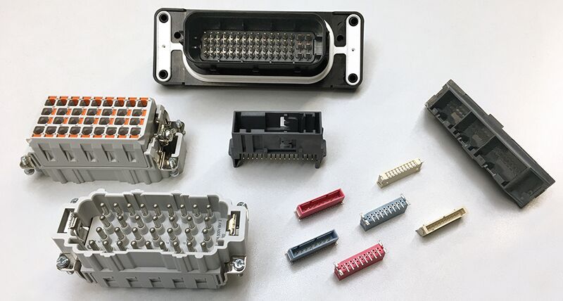
Automotive electronics, consumer electronics, telecommunications, data technology, industrial electronics: in a large number of electrical and electronic systems, connectors in different designs and with a large variety of technologies ensure signal transmission and power supply.
 Technological trends such as modularisation, miniaturisation and function extension open up opportunities for further growth for connectors in all areas of application. At the same time, however, these trends also increase requirements for the measurement and inspection technology, which is used to assure quality and process control of increasingly complex connector assemblies.
Flexible inspection capabilities and high measurement throughput
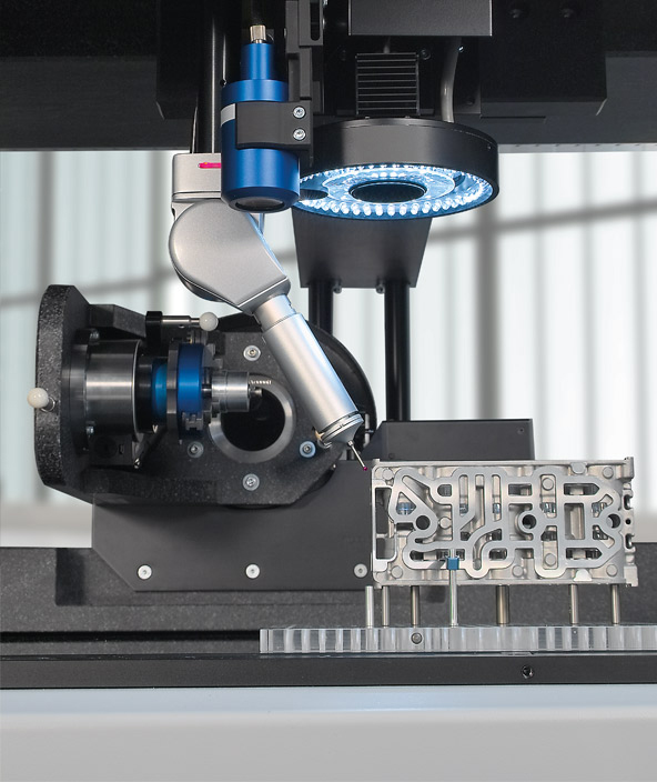
“Maximum technical performance at smallest size” best describes the requirements for connectors. For quality control of the miniaturised assemblies, the measurement technology used must offer high resolution and accuracy. Diverse connector types and housing variants require flexible adaptation to variable dimensional inspection tasks. A high measurement speed further expands the profile of requirements. By incorporating multiple sensor technologies into a single, high-precision measurement platform, OPTIV M multisensor coordinate measuring machines (CMMs) from Hexagon provide a universal solution for the capture and analysis of the entire spectrum of possible geometric errors of connectors. They are therefore particularly suitable for initial sample inspection of complex connector assemblies in fully automated measuring cycles.
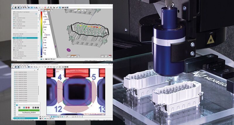
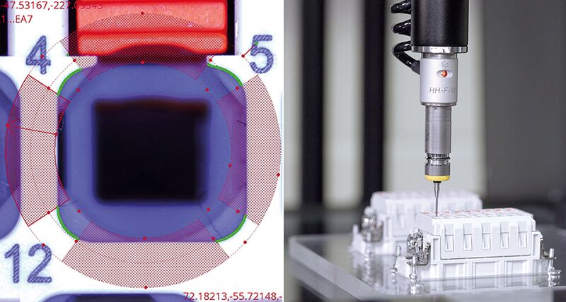
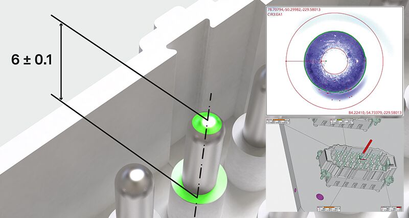 The perfect connection of a connector is guaranteed by the dimensional accuracy of its electrical contact elements (connector pins). For verification, the height of the pins (seating depth) related to a defined datum plane is measured. The typical length tolerance is in the range of ± 0.1 mm. It is the perfect interplay of the non-contact sensors on OPTIV M that forms the solution here; the camera sensor quickly locates the lateral position of the individual pin tips. For this purpose, the metrology software PC-DMIS provides a special image processing algorithm that allows for irregularly shaped pins to be reliably detected on the basis of a centre-of-gravity calculation. In the same measurement cycle, the vertical position of the pins is measured regardless of their shiny surface with the chromatic-confocal white light sensor. Due to the axial beam path of this non-contact distance sensor, there are no shading effects, so that even narrow and deep in the connector housing lying pin grids are reliably detected.
In addition, the permissible positional deviation of each pin tip from its ideal zero position in the X and Y directions is measured. The corresponding datum is made using a constructed intersection that is derived from measured reference edges on the connector housing.
Dimensional accuracy of the contact elements
The perfect connection of a connector is guaranteed by the dimensional accuracy of its electrical contact elements (connector pins). For verification, the height of the pins (seating depth) related to a defined datum plane is measured. The typical length tolerance is in the range of ± 0.1 mm. It is the perfect interplay of the non-contact sensors on OPTIV M that forms the solution here; the camera sensor quickly locates the lateral position of the individual pin tips. For this purpose, the metrology software PC-DMIS provides a special image processing algorithm that allows for irregularly shaped pins to be reliably detected on the basis of a centre-of-gravity calculation. In the same measurement cycle, the vertical position of the pins is measured regardless of their shiny surface with the chromatic-confocal white light sensor. Due to the axial beam path of this non-contact distance sensor, there are no shading effects, so that even narrow and deep in the connector housing lying pin grids are reliably detected.In addition, the permissible positional deviation of each pin tip from its ideal zero position in the X and Y directions is measured. The corresponding datum is made using a constructed intersection that is derived from measured reference edges on the connector housing.
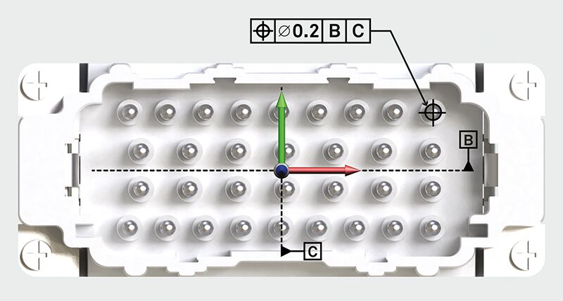
Measurement of the permissible positional deviation of the pin tips
The camera sensor’s variable lighting options ensures highly accurate edge detection. All LED light sources - coaxial top light, telecentric back light and multi-segment ring light - can be flexibly adapted to suit the texture and colour of various connectors. At measurement routine execution, the PC-DMIS function SensiLight checks whether an adjustment of the lighting is necessary and supports the user in selecting the correct lighting setting.
Functional inspection of the connector housing
For some connectors - especially in the automotive industry and the eMobility sector - resistance to environmental influences, dirt and humidity are important mechanical requirements. The flatness of contact and sealing surfaces must therefore be measured.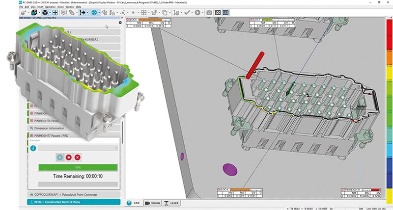
Measurement of the flatness of contact and sealing surfaces on the connector housing
In scanning mode, the chromatic white light sensor enables the surface and ambient light-independent capture of line profiles on the surfaces to be measured with a high measuring point density. The metrology software PC-DMIS provides a range of CAD-based methods for contact and non-contact scanning. With the Perimeter Scan, the scanning path for the non-contact white light sensor is created directly on the imported CAD model of the connector. The scan then follows automatically along a defined offset of the nominal contour of the selected sealing surface. For a quick conformity assessment of the dimensional accuracy of critical contact and sealing surfaces, the measurement data can be analysed against the CAD model during the measurement routine execution and visualised as a colour-coded presentation of deviations.
The socket side of connectors also poses metrological challenges. In injection moulding or overmoulding processes, smallest cavities can be produced in very dense clusters.
The socket side of connectors also poses metrological challenges. In injection moulding or overmoulding processes, smallest cavities can be produced in very dense clusters.
Multisensor measurement of the spatial orientation of the connector sockets
Their inclination related to a defined reference plane is one of the important functional dimensions of connectors and must be measured. To solve this task, the multisensory coordinate measuring machine OPTIV M combines camera sensor and touch-trigger probe in one measuring cycle, and all measurements are carried out according to the drawing and without reclamping the workpiece. First, the position of the cavities is captured by optical measurement. Then standard geometry elements are measured with the touch-trigger probe in defined vertical section planes. A constructed centre line then provides the spatial orientation of the respective cavity. With two independent axes for the optical and tactile sensors, the OPTIV Dual Z technology provides the best accessibility to the inspection features with a minimised risk of collision. In addition, programming and measurement times are reduced to a minimum.