Full thrust thanks to measuring on machine-tools
Contact us
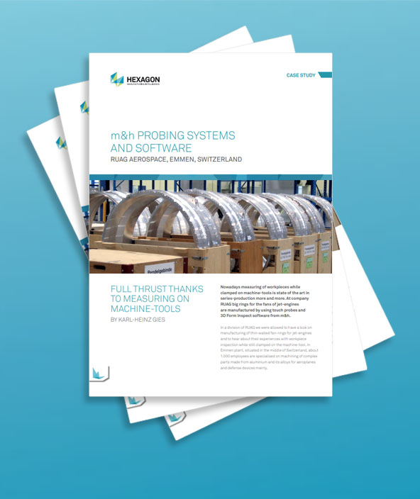
Nowadays measuring of workpieces while clamped on machine-tools is state of the art in series-production more and more. At company RUAG big rings for the fans of jet-engines are manufactured by using touch probes and 3D Form Inspect software from m&h.
In a division of RUAG we were allowed to have a look on manufacturing of thin-walled fan-rings for jet-engines and to hear about their experiences with workpiece inspection while still clamped on the machine-tool. In Emmen plant, situated in the middle of Switzerland, about 1.000 employees are specialised on machining of complex parts made from aluminium and its alloys for aeroplanes and defense devices mainly.
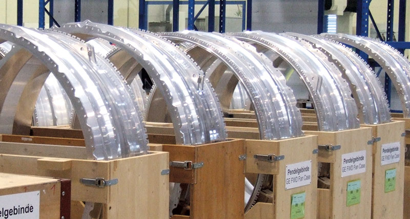
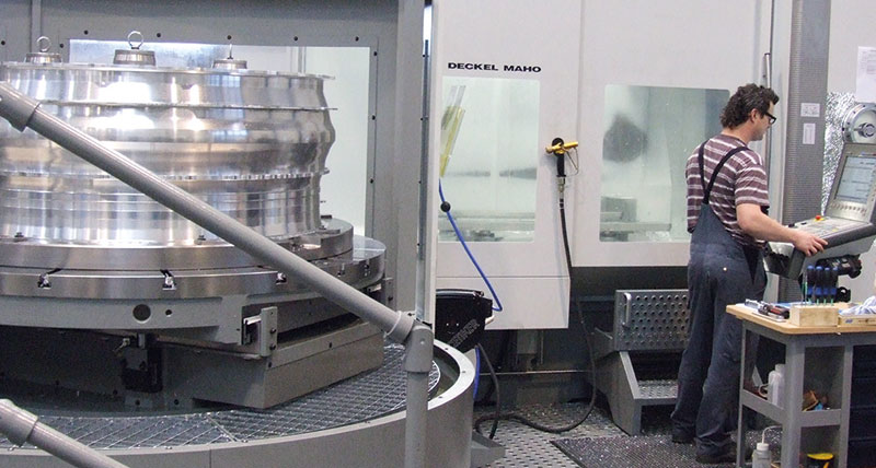
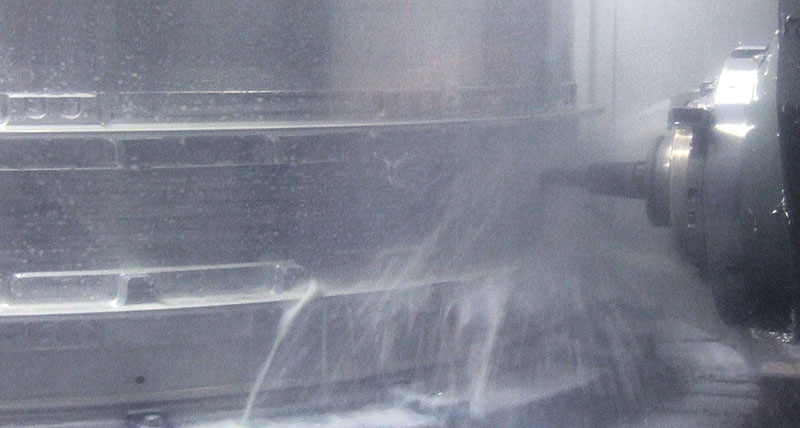
 “The strategy of RUAG is to manufacture critical parts of high complexity with reliable processes and at highest efficiency,” Markus Graber, Teamleader Machining at RUAG tells. RUAG Emmen manufactures fan-housings for the jet-engine CF34-10E from General Electric, used at the newest generation of planes type Embraer 190 / 195, for example. These near-to-cylindrical workpieces have diameters about 1500 mm and a height of about 600 mm, but their walls are thin.
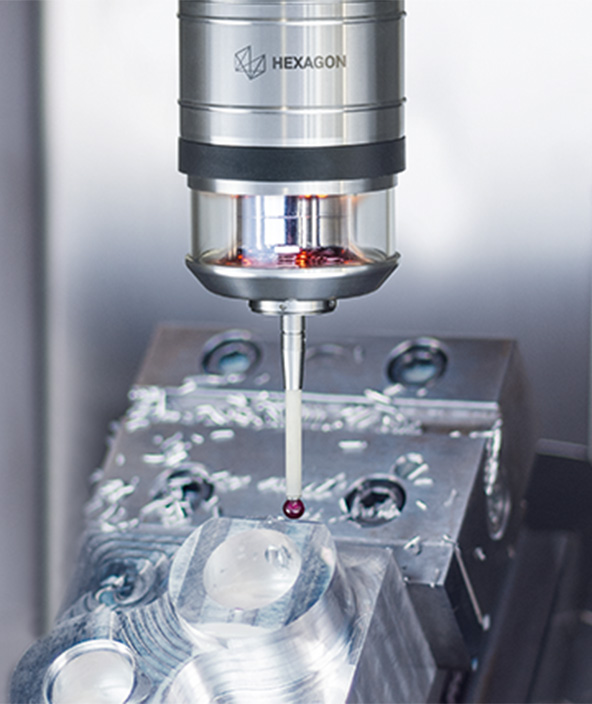
“The main problem was to adjust the run-out on the measuring machine. At the start we could not measure the parts on a CMM. Measuring by 3D Form Inspect from m&h while still clamped on the machine-tool was the only way to do the job,” Markus Graber explains. The machining of the fan-housings is done on 2 machining-centres, type DMC 200 FD, with pallet-changers. Controlled by a Siemens 840D control the machines are equipped with m&h touch-probes with infrared transmission via a small receiver mounted near to the spindle-nose. 3D Form Inspect software from m&h was used on this type of DMG machine-tools first time but it matched just from the beginning.
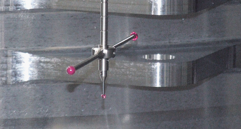
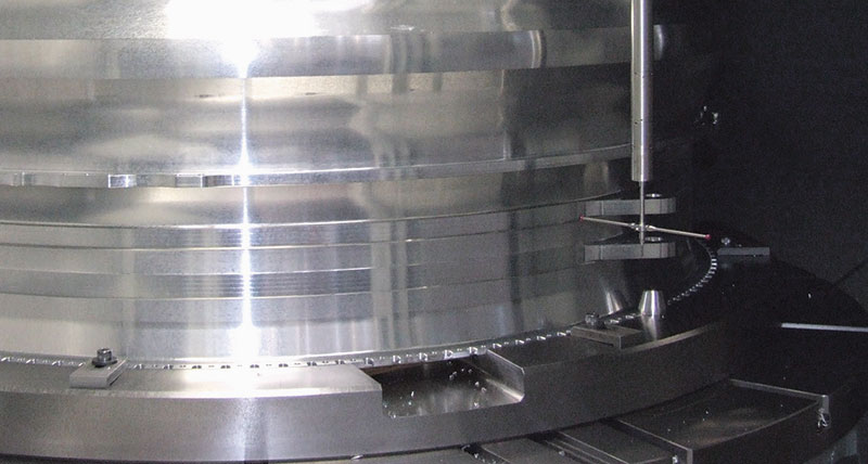 Beside the strong need of tough accuracy the fanhousings come up with a lot of complex geometries and surfaces curved in 2 directions, undercuts as well as hidden grooves and holes, which later-on are fixation points for drives and other devices of the engine. In order to be able to inspect them all 4 different touch-probes are used with different lengths and different diameters of touching balls as well as some with cross styli. M&h invented modular touch-probes with standard extensions available in lengths of 30, 50, 100 and 200 mm.
 The modules are made from stainless steel with a diameter of 25 mm only and can be screwed on one-another until close and rigid contact on their flanges and carrying its measuring system on top. At RUAG they are using probes with extensions up to a total length of 500 mm.
Lots of benchmark tests have proved that measuring results on the machine-tool generated by m&h systems are differing just by some microns from those measured on a CMM and they are absolutely repeatable. “The measuring results from 3D Form Inspect allow decisions to continue or stop machining of the parts at any time during the process”, Markus Graber confirms. “At the beginning the CMM was not ready yet. Everything has been realised on the machine-tool. This was possible thanks to the ingenious calibration strategy of m&h”. All thermical moves of the machine are automatically detected and compensated. Due to the fact that 3D Form Inspect is detecting deviations in 4th and 5th axis, all swivelling failures of those axes are automatically compensated, too.
"This simply gives us the certainty in production we need. And it pays off in a short time, definitely."
3D Form Inspect is managing all 4 different touch probes and is generating the NC-programs inclusive calibration, which is very important with those long probes. Otherwise by using such long probes a slight deviation of some microns at the spindle-cone can give a big difference of some tenth at the touching point of the probes giving a wrong measuring result. By simple mouse clicks on the surface-model at the screen of a computer the servant may determine the points to be inspected. To all points he can add measuring functions like heights, angles, circles diameter or others.
 In the protocols the software will automatically check the values against the dimensions wanted. After determining the probe that should be used for the touches 3D form Inspect generates the programs in the background inclusive a collision control of the touch-probe with the contours of the workpiece. This makes work for servants much easier and ensures not only highest precision but also a secure and reliable process without interruption. Servants gain certainty about their doing and can control their processes anytime during manufacturing.
A mistake in evaluation would make scrap from a very expensive part. “In case we later-on find a mistake and reworking is necessary we have to organise totally differently,” Markus Graber explains. “Immediate rework on the machine tool is impossible because we never find back the Zero-point and the form of the workpiece exactly.” With measuring in between the steps of machining immediate reaction and remachining is possible, saving a lot of time and money.
At RUAG it is widely used nowadays and became state of the art. Of course, for RUAG these techniques have been new and everyone has been very sceptical first. “We entered unknown territory with this matter and we had been highly sceptical, of course”, Markus Graber reports. “But the handling really is simple and the system is simple as well. Our workers made friend to this software easily and today they are highly motivated by using this tool”. Knowing about the complexity with more than 1.000 dimensions to be inspected at one workpiece this really is a good statement. “This simply gives us the certainty in production we need. And it pays in short time, definitely.”