Adams machinery
A Powerful Simulation Suite for Mechanical Drive Systems
Evaluate and manage the complex interactions relating to motion, structures, actuation, and controls to better optimize product designs for performance, safety, and comfort.
Build functional virtual prototypes of machinery components and systems early in the design cycle, so you can perform a series of virtual tests before committing to building a physical prototype. With this new solution, machinery manufacturers will reduce the number of prototypes, decrease the design cycle and meet their functional specifications in less time.
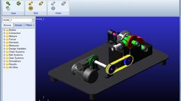
Adams machinery is fully incorporated inside the Adams View environment. It contains multiple modeling productivity modules which enable users to create common machinery components much more rapidly than with generic standard Adams View model construction functionality alone.
Ease of use
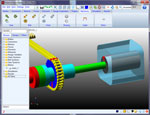
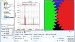
Adams ribbon-style interface and model browser makes it easy for even novice users to create complete, accurate mechanical models. A core package (Adams View, Adams Solver, and Adams PostProcessor) allows you to import geometry from most major CAD systems or to build a solid model of the mechanical system from scratch. You build a system the same way you build a physical system – by creating and assembling parts, connecting them with joints and driving them with motion generators and forces.
High productivity
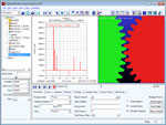
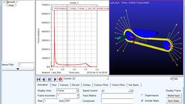
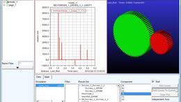
Adams Machinery enables users to create some common machinery components more efficiently by guiding users in pre-processing via automation of activities like geometry creation, subsystem connections, etc. It also assists users in post-processing by providing automated plotting and reporting for commonly desired output channels.
The Adams model has subsequently been used to perform an extensive parameter study to find the root cause and solutions to the observed gear resonance.” - Christina Exner Manager. Achates Power.
-
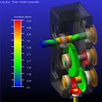
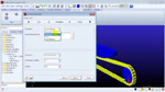
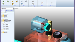
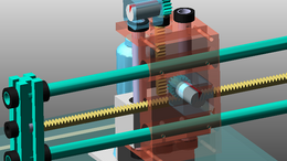
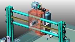
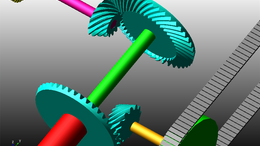
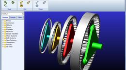
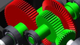
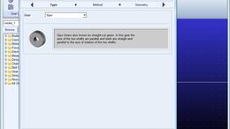
Gears module
-
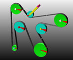
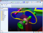
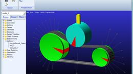
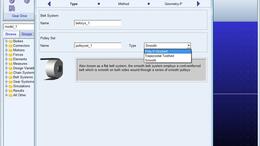
Belts module
-
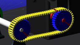
Chains module
-
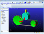
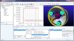
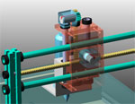
Bearings module
-
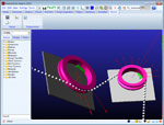
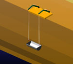
Cable module
-
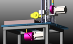
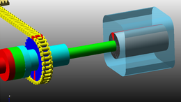
Electric motors module
-
Cam module
-
Collateral
-
Videos