SMIRT (main application)

Solid visualization environment to manage design information for the manufacturing process

SMIRT provides die construction

The hub for manufacturing process

Whether it be management, estimators, project coordinators, engineers, or machinists and tool assemblers, SMIRT provides a single access point to all the information to produce tools and dies, entirely based on 3D graphics.

Product capabilities

Features at a glance:

  • Industry proven solution
  • Short learning times 
  • Multiple CAD source import
  • Simple, intuitive user interface
  • Super fast graphics
  • Automatic stock list extraction


  • Interactive balloons & dimensions
  • Large assembly management
  • Dynamic section views
  • Urgent notes
  • Project management & information sharing
  • The manufacturing information hub

Different CAD sources are managed (NX, CATIA V5, CATIA V6, NX, STEP, Parasolid, IGES, VISI, HXGN DESIGNER) to offer a single look and feel to final users. All the information available in the CAD data (geometry, stock list and technology) is retrieved and made available in the easiest way to be used for design review and analysis for shop floor activities. This is our DNA…. Solid Model Information Retrieval Technology.
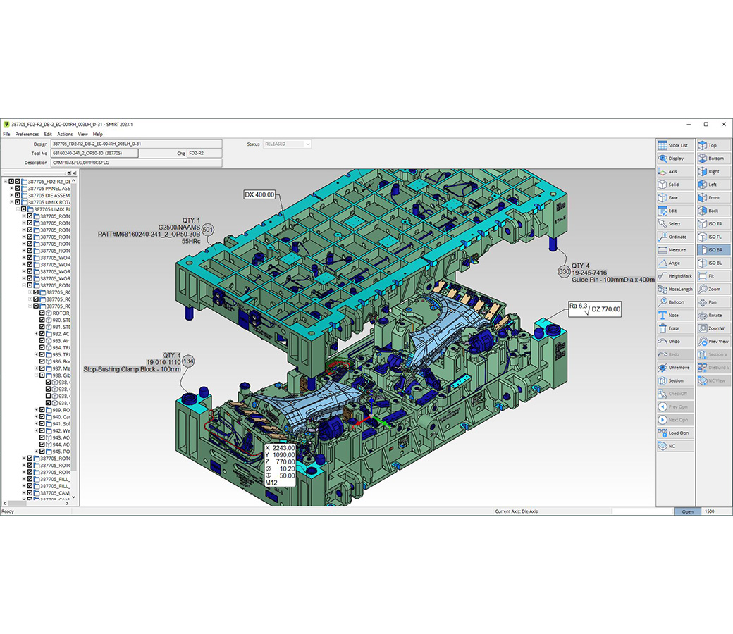

Simple intuitive user interface

Recognizing that shop floor personnel are getting paid to build dies and not to be CAD/CAM operators, SMIRT has been designed to be very easy to use with minimal training required. SMIRT uses a simple, intuitive plain text interface for all operations (no icons to memorize) and is specifically designed for the needs of die makers, based on a real life die making experience.

Sharp, clear and fast graphics

The graphics representation available in SMIRT is designed to make it easy to understand the structure and functionality of the die assembly. The fast graphics engine enables the user to zoom, move, rotate and change view mode in real time, without waiting for graphic regeneration. Standard orthogonal and isometric views are always available and only one mouse click away.

Stock list and balloons

The stock list information (item ID, quantity, material, commercial code and others) retrieved from the CAD data is available in SMIRT to interactively navigate through the parts and components of the die: select one or more items from the stock list to display them (or add to display). Interactive balloons are available with stock list information to get item information by simply picking the relevant component in either 3D or section view modes.

Display control

Specific commands are available to switch from the complete die view to other sub-assembly groups and to assembly or disassembly components from the major castings. The die can be opened and slides and blank holders can be moved to the two opposite dead points of their strokes.


Axis management

Axis systems are automatically retrieved from CAD data or can be created inside SMIRT with simple and intuitive tools. Setting the proper current axis makes it easier to analyze the functionality and the construction techniques for cam slides and complex dies, leading the operator to extract and the correct reference dimensions used for machining operations.

Powerful dimensioning

Three families of real time dimensioning tools are used to check the geometry of the die components. "Measure" tools are used to take dimensions between two geometric features (point to point, face to edge, etc.). "Ordinate" tools are used to take coordinate positions referred to the current axis. The ordinate position of drilling holes will also give technological information (tapered hole, tolerance hole, etc.) if defined in the original die design. "HeightMark" is a dimensioning tool to take specific plane position and finishing information. The finish information can be retrieved from the CAD files or can be automatically recognized by special SMIRT algorithm.

Cross sections

Simple techniques let the user cut cross sections on the fly if required and positioned as needed. No support is required from the design department and section cutting is fast and easy (no complex CAD approach is applied). The section plane can be dynamically moved using a slider and different viewing styles can be displayed and combined: section, section and split solids, hatch, filled cut face. Dimensioning, annotation and balloon tools are also available in the section view.

Annotation and information sharing

All views can be completed with floating or flag notes (the text box of a floating note is fixed to the graphics window, while for a flag note, it is linked to a point on a solid). Views with dimensions or notes can be saved and shared on the network with other colleagues or departments. Urgent notes can be defined so that every one who accesses the file will be prompted to check the urgent note itself. All views can be exported as images to external files for documentation / e-mail messages.