SMIRT (main application)
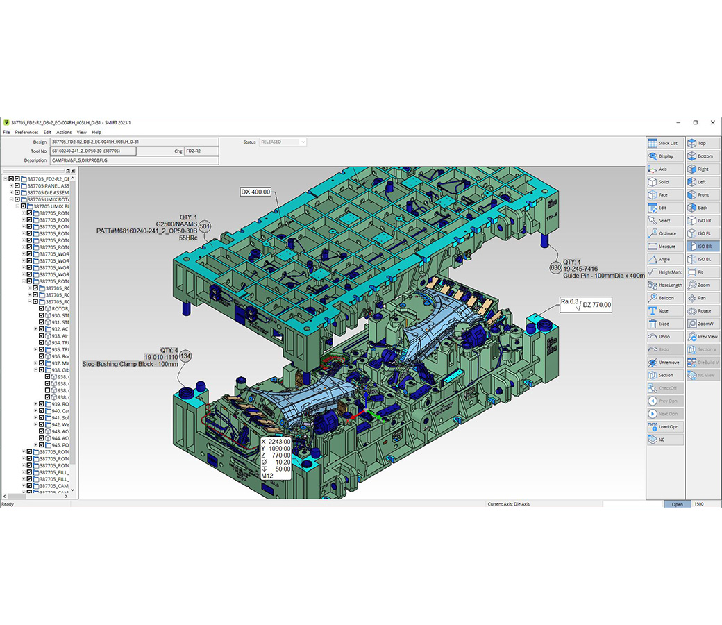
Solid visualization environment to manage design information for the manufacturing process

The hub for manufacturing process
Whether it be management, estimators, project coordinators, engineers, or machinists and tool assemblers, SMIRT provides a single access point to all the information to produce tools and dies, entirely based on 3D graphics.
Product capabilities
Features at a glance:
- Industry proven solution
- Short learning times
- Multiple CAD source import
- Simple, intuitive user interface
- Super fast graphics
- Automatic stock list extraction
- Interactive balloons & dimensions
- Large assembly management
- Dynamic section views
- Urgent notes
- Project management & information sharing
- The manufacturing information hub
Different CAD sources are managed (NX, CATIA V5, CATIA V6, NX, STEP, Parasolid, IGES, VISI, HXGN DESIGNER) to offer a single look and feel to final users. All the information available in the CAD data (geometry, stock list and technology) is retrieved and made available in the easiest way to be used for design review and analysis for shop floor activities. This is our DNA…. Solid Model Information Retrieval Technology.