Hexagon's Manufacturing Intelligence division
Our solutions equip manufacturers to innovate and create without limit. Take your products to new levels and improve people’s lives with better quality experiences.

Quality for life
Quality is for people. It’s something we seek again and again. By adding the magic of quality to your products, you can truly move the needle for your business.

MAESTRO – The all-digital CMM System
Quality remastered via speed, ease of use, connectivity and adaptability

Shop Hexagon
Register for a seamless shopping experience and dive into our extensive range of metrology accessories and software training modules.
Explore Manufacturing Intelligence
Metrology
Get it right first time with the insights from last time. Hexagon’s metrology solutions help you to close the gap between design intent and real-world operation with actionable, real-time insight that revolutionises upstream and downstream decision-making.
The world of metrology is changing. The rest of the manufacturing world is waking up to the incredible power of product quality data. Metrology and metrologists are now at the coal face of innovation. The quality team can embed vital insight ensuring design, manufacturability, production, quality, productivity and performance can all be optimised. Our metrology technologies put that kind of power and insight at your fingertips. They are the key bridge between the physical and virtual worlds, bringing real-world data into the digital domain to power smarter manufacturing approaches


Production
Push production to the limits. Make what they said was unmakeable. Bring innovations to life in incredible new ways. Our solutions equip manufacturers to turn imagination into reality, improving quality of life for all. Spanning machining, forming, casting, moulding, joining, 3D printing, or a combination of multiple processes – the production floor is where components take shape.
Production is where product quality is set in stone, metal, wood or composite and the pursuit of manufacturing ‘right first time’ is the highest priority. It’s the manufacturing process phase where productivity really matters – efficiency and throughput are essential to remain competitive – costs must be controlled and downtime avoided. This is where you need design intent to be maintained through the production cycle.
Quality – the biggest needle mover in manufacturing
Whether you design, invent, manufacture, test or service products – ultimately, it’s about people. No matter what we make as manufacturers, every component, part or product is made to improve our quality of life.
Quality means many things to manufacturers. It’s an international standard. It’s a legal definition. It’s a checkpoint controlling what leaves the factory. To the end user, it’s none of those things. It’s a feeling. Delivering this feeling is the foundation of long-term commercial success.
A quality-focussed strategy is the biggest needle mover in manufacturing today. Imagine any concern you have right now whether it’s agility, scalability or time-to-market – with one truly connected approach for quality you can not only put your worries to rest – you can develop incredible new capabilities that position your business for long-term success.
Rather than focussing on a specific area or a specific problem, Hexagon creates a holistic system for success.
Designed for seamless connectivity, this enables us to put your data to work to its fullest.
Extending way beyond the design, make and inspect phases of manufacturing, our solution unleashes potential across every phase of the business cycle, from planning and management to customer fulfilment. Entirely seamless, it transforms data from siloed asset into the very connecting fibre of your business, unleashing a multiplier effect across your value chain.
Fusing digital and real worlds, we create immersive digital twins of products, assets and facilities – this means you can test, explore and iterate entirely in the virtual world. This gives you the freedom to innovate, explore and scale up production, closing the loop on cost, quality, innovation and sustainability. By embedding advanced automation – optimisation is driven to new levels.
The most important step is to embed continuous improvement by leveraging generative, autonomous AI recommendations allowing you to create incredible products in incredible new ways.
Hit all of your business goals with one connected strategy for quality. Develop products that improve people’s lives.
Discover how we innovate quality
Explore our support resources
These problems stand in the way of everything from business objectives and profitability to order fulfilment – but most of all they stand in the way of progress.
Our solutions put data to work to transform your operations with insight. As well as helping customers solve quality challenges that become apparent at each specific stage of the cycle, by developing a single digital thread for quality, we help you drive a multiplier effect by unlocking gains across every phase in a circular way.
Hexagon technology enables manufacturers to harness and deploy data from all the key stages of the manufacturing process. Underpinned by the unique combination of both software and hardware, our unparalleled portfolio of digital manufacturing technologies spans CAD CAM and complementary software for production applications, metrology hardware and software solutions, as well as data management and analytics tools.
This culminates in the fusion of physical and digital worlds, with immersive digital twins that use real-world, real-time data and AI. Beyond offering complete line-of-sight to every possible scenario, enabling planning and predicting issues before they occur – technology and data provide new avenues for your ideas fuelling innovation and freeing you to solve the defining challenges of your sector.
We accelerate quality across the value cain with deep and actionable insight to ensure high productivity, offering dedicated industry specialist advice, support, insight and intelligence.
Achieve your transformation goals, gain a competitive advantage, differentiate your business – let’s see what we can achieve, together.


-
 FeaturedProduct
Discover improved direct scanning accuracy and productivity with the state-of-the-art laser tracker technology of the ATS800.
-
×Full autonomySuitable for integration in in-line automated inspection systems, as well as AMR or AGV mountable for autonomous inspection systems. Suitable for full automation integration as part of an in-line robot inspection cell or mounted on an autonomous mobile robot-based solution.
-
 FeaturedProduct
Wireless-enabled handheld 3D scanner for easy measurement anywhere.
-
×Full autonomyAutomation-ready for integration within fully autonomous inspection systems.
-
-
 FeaturedSolution
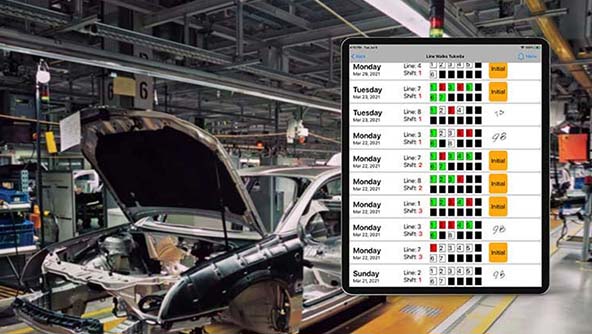
Smart Audits
×Line WalksOften called operator rounds or line walks, these digital checklists ensure machines are calibrated and running optimally.
-
 FeaturedProduct
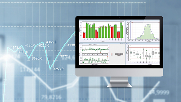
qs‑STAT delivers compliant machine acceptance and process capability, validating Cm/Cmk and Cp/Cpk to ISO 22514‑2, revealing root causes through reliable analyses.
-
×Human-Assisted autonomyProcess qualification analysis
-
-
 FeaturedProduct
Industry leading Reverse Engineering software. Quickly and accurately create CAD models with 3D scan data from any scanner.
-
 FeaturedSolution
Dynamic midstream and final inspections that reduce costs of poor quality and warranty claims.
-
 FeaturedProduct
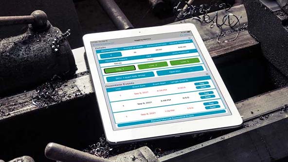
Gives context to machine data to explain machine downtime, report and make decisions to improve OEE.
-
 FeaturedProduct
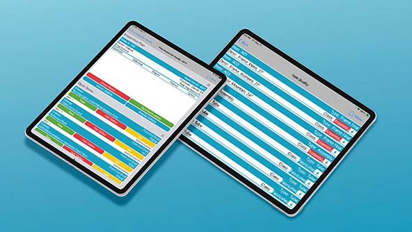
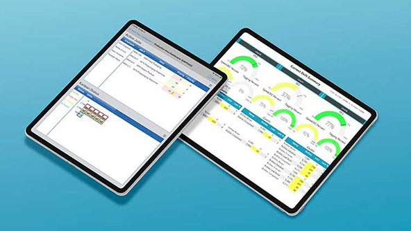
Track performance and collect data in a repeatable fashion; view real-time performance indicators to improve decision-making.
-
 FeaturedProduct
Inspire is an intuitive inspection software for portable probing and scanning applications that makes measurement simple.
-
×Partial autonomyAutomated application of smart UX, metrology algorithms and machine control to simplify the measurement experience
-
-
 FeaturedProduct
MAESTRO is the next-generation, all-digital CMM which embraces transformative technologies to lead the metrology revolution.
-
×High autonomyAutomatic identification and initialisation of sensors and changer racks. Automatic part feeding. Automated part programme creation, probing path optimisation and collision protection. Automatic execution of part programmes Automatic real-time reporting. Automatic CMM health and performance monitoring.
-
 FeaturedProduct
Photogrammetry-augmented handheld 3D scanner for wireless and targetless measurement anywhere.
-
×Full autonomyAutomation-ready for integration within fully autonomous inspection systems
-
-
 FeaturedProduct
Real-Time Monitoring
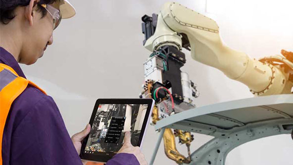
×AR MonitoringAugmented reality solution to view machine data in real time.
-
 FeaturedProduct
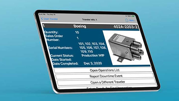
Digital standard work instructions for manufacturing.