Dana improves off-road durability with robust design and stochastic analysis
Dana Incorporated: Federico Bavaresco (Driveline Lead Engineer), Tommaso Pirovini (Driveline Engineer), Lorenzo Bellorini (Simulation Engineer), Claudio Maffei (Virtual Verification & Integration Engineer) Hexagon’s Manufacturing Intelligence division: Marco Veltri (Business Developer), Patrik Adolfsson (Product Designer, R&D), Mark Robinson (Technical Consultant)

Engineering Reality 2023 volume 2 edition
Empowering Makers for an autonomous sustainable future
Dana is a leader in designing and manufacturing highly efficient propulsion and energy-management solutions that power vehicles and machines in all mobility markets across the globe. The company is shaping sustainable progress through its conventional and clean-energy solutions that support nearly every vehicle manufacturer with drive and motion systems; electrodynamic technologies, including software and controls; and thermal, sealing, and digital solutions.
Based in Maumee, Ohio, USA, the company reported sales of $10.2 billion in 2022 with 42,000 people in 31 countries across six continents. Dana, with a history dating to 1904, was named one of “America’s Most Responsible Companies 2023” by Newsweek magazine for its emphasis on sustainability and social responsibility. The company is driven by a high-performance culture that focuses on valuing others, inspiring innovation, growing responsibly, and winning together, earning it global recognition as a top employer.
Challenge: Reliable drivetrains, no matter the application
Users subject off-highway vehicles to a wide range of applications depending on the vehicle’s configuration, the tasks it handles, and how end users employ the vehicle. As a result, Dana engineers found it challenging to develop a right-size off-highway vehicle drivetrain that would be reliable in the field for every potential application.
To address this, Dana created drivetrains based on the most representative applications. However, in some cases, customers still experienced field issues in specific applications that were not 100% covered during the development phase due to a lack of input data. This leads to inefficiency, higher cost of design and validation and longer development time.
“We have a lot of variabilities, and we need to manage them. Otherwise, if we consider the nominal value, we have failure and cannot explain why. To increase our products’ reliability, we have to take variability into consideration and manage it,” explained Federico Bavaresco, Driveline Lead Engineer at Dana.
To improve its off-highway axle’s durability and in-field performance, the company knew it needed to incorporate uncertainties more effectively into its design and development process.
Solution: Robust drivetrain designs
Dana wanted to create a more robust design for its drivetrains. Its engineers knew they needed to account for randomness and variability in their design approach and test bench validation.
The company partnered with Hexagon to undertake the project and moved forward with a multi-phase approach.
Phase 1. Fatigue simulation under operational loads
The teams kicked off the engagement by investigating critical areas; determining the kinds of fatigue loads associated with different manoeuvres. To achieve this, Dana provided real loads histories from field measurements— forces and torques — for multiple vehicle manoeuvres. They then set up a CAEfatigue process flow-driven duty cycle analysis; combining load time histories with the FE stresses, the teams could reconstruct the stress time history on each node structure, effectively calculating the structure damage for the entire component life.
CAEfatigue gave Dana engineers a user-friendly template to set input parameters, material properties, FEA results, and load time histories, generating results in an easy-to- understand graphic interface. As a result, engineers could identify which vehicle manoeuvres caused higher levels of stress or damage while also defining the critical component areas most likely to fail.
Phase 2. Stochastic analysis after randomisation of loads and fatigue parameters to determine the effects of variation
After performing the fatigue simulation in phase 1, the teams deployed CAEfatigue Robust Design to automatically enforce a stochastic variation on all the input variables and perform Monte Carlo simulation. All parameters follow a Gauss Normal distribution based on three pieces of information: the mean value, the coefficient of variation, and the cutoff (the number of standard deviations that determines the accuracy percentage). The only exception is customer usage or the number of repetitions for every different manoeuvre.

Figure 1. Comparison between Max Neuber Stress results related to every manoeuvre.

Figure 2. Identification of critical fatigue areas.

Figure 3. Correlation between parameter variations.

Figure 4. Clouds of input-output pairs obtained with the stochastic study.
Embracing such probabilistic approach, the teams could evaluate the effects of the uncertainties on the structure’s robustness, identifying the input variations that led to the highest potential for damage and other undesirable conditions, thus empowering them to create more robust designs capable of withstanding the uncertainties with in-field conditions.
Hexagon’s CAEfatigue Robust Design provides two graphic tools (Figure 3) — the decision map and pie chart — that help engineers understand how different variables influence the axle component performance. The decision map shows the relationship between the input parameters (yellow squares) and requested outputs (light blue squares), with the size of the blue circles showing the relative input-output influence. The pie chart displays all relative parameter influence on a given output— for example, their impact on max damage value.
CAEfatigue Robust Design can also generate a point-cloud visualisation of the input-output pairs distribution. This visual representation makes it easy for engineers to identify the combinations of inputs most likely to lead to an unacceptable output (e.g., damage exceedance probability) or undesirable behaviors (e.g., outliers or bifurcations).
Phase 3. Loads synthesis through stochastic design improvement, aimed at designing a representative physical test
Once the engineers reached their robust design objectives, they began the loads synthesis phase, searching for combinations of test loads conditions causing results closest to the target in-field damage. For this endeavor, the teams deployed the stochastic design improvement workflow inside CAEfatigue Robust Design. Through this probabilistic approach, a set number of stochastic simulation steps are undertaken in sequence, each including small variations of key design variable parameters affecting the test bench set-up.
“The third phase is where we identify the procedure that determined the best set of loads in the physical tests that mimicked the real damage accumulated during the simulation,” said Bavaresco. “We use a simplification of the manoeuvres, which is represented in different kinds of loads. The whole purpose is to correlate the damage predicted with the damage we actually get in the test setup.”
“We’ll take the initial results and refine them, taking variability into account to perform the stochastic design improvement. To accomplish that, we start from an initial assumption, then change that initial condition —for example, we may tweak the number of repetitions in the scaling factor, modulating them until we get a damage that is as close as possible to what we’d calculated with the actual manoeuvres. It isn’t a typical simulation validation exercise; it’s that we’re trying to get our results to emulate as best as possible what we’ve calculated in simulation,” Bavaresco said.
Dedicated CAEfatigue Robust Design graphic tools allow engineers to quickly interpret a vast number of results, letting them follow design variables trends step-by-step.
All design parameter combinations have the same probability. For every simulation step, CAEfatigue Robust Design identifies the best solution (red cross in the point cloud) as the starting point for the next step (Figure 6). At the steps sequence conclusion, CAEfatigue displays the test parameters combination causing damage closest to the damage calculated with the real in-field load events. Assuming that the conclusion reached meets the target requirements, engineers can perform a final robustness check to validate and confirm their findings, using the improved test parameter combination as input for a new stochastic study.
Results: Randomness and variability
Dana has been pleased with the results that Hexagon and the CAEfatigue and Robust Design solutions have been able to provide. “Knowing the variability of the damage
allows us to reduce the margin because we’ve already taken the variability of the inputs into account. That means we can optimise the design and close the variability gap,”
said Bavaresco.
“With Hexagon allowing us to introduce randomness and variability into the equation, we can right-size our components — which helps us ensure reliability in the field and remain competitive. In the end, working with Hexagon creates not just a massive value for us, but also our customers,” he shared.
The company plans to continue its stochastic design improvement in the future, further evaluating how various input parameters impact structure damage and determining a simplified, representative robust surrogate load set for test validation. Ultimately, the company will be able to develop a fully-repeatable process that can be easily and consistently applied to multiple products of its production line.
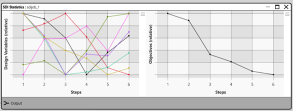
Figure 5. Design parameters variation and damage objectives trend according to the step number.
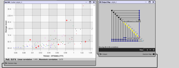
Figure 6. Improved configurations for every step.

Figure 7. Robust Design stochastic function study driven by CAEfatigue.
“With Hexagon allowing us to introduce randomness and variability into the equation, we can right-size our components, which helps us ensure reliability in the field and remain competitive.”
“Hexagon’s simulations allow us to virtually create and predict the same damage we see in real life. Those simulations will serve as the basis for future optimisation because if we can optimise in simulation, we protect against failure on the field,” Bavaresco concluded.