Laser scanning closes the digital gap in 3D printing and high-end milling workflow

GF Machining Solutions, Biel, Switzerland

Laser scanning closes the digital gap in 3D printing and high end milling workflow

Engineering Reality 2024 volume 1

Accelerate Smart Manufacturing

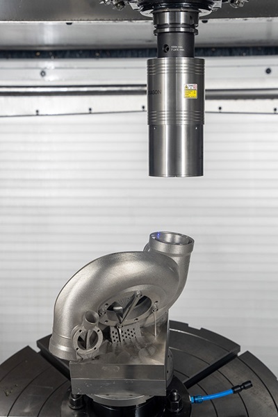
GF Machining Solutions used Hexagon’s laser scanning solution for machine tools to dramatically reduce the process time for the alignment, digitisation and machining of a 3D-printed Formula 1 turbocharger.

GF Machining Solutions was tasked with creating an optimal workflow for additive and subtractive manufacturing of a Formula 1 turbocharger. By incorporating Hexagon’s laser scanning technology, they overcame vexing alignment and measurement challenges when moving between a digitalised 3D printing process and subsequent machining steps, resulting in a more efficient workflow and significant reductions in both time and costs.

GF Machining Solutions is one of the world’s leading providers of machine tools and diverse solutions for manufacturers of precision parts and the mould-making industry. Its portfolio includes machines for milling, Electrical Discharge Machining (EDM), 3D laser texturing, laser micromachining and additive manufacturing.

Based in Switzerland, the company is a globally acting division of the Georg Fischer Group with its own sales companies in over 50 countries. In addition, the division operates production facilities and research and development centres in Switzerland, the USA, Sweden  and China. 

In response to a customer request to produce a turbocharger for use in a Formula 1 car, GF was asked to develop the best possible manufacturing workflow, from design, simulation and production through to qualification.

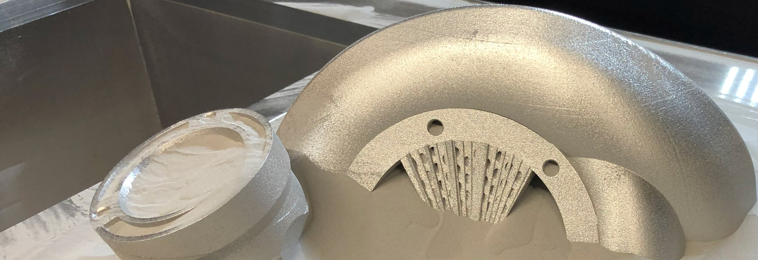
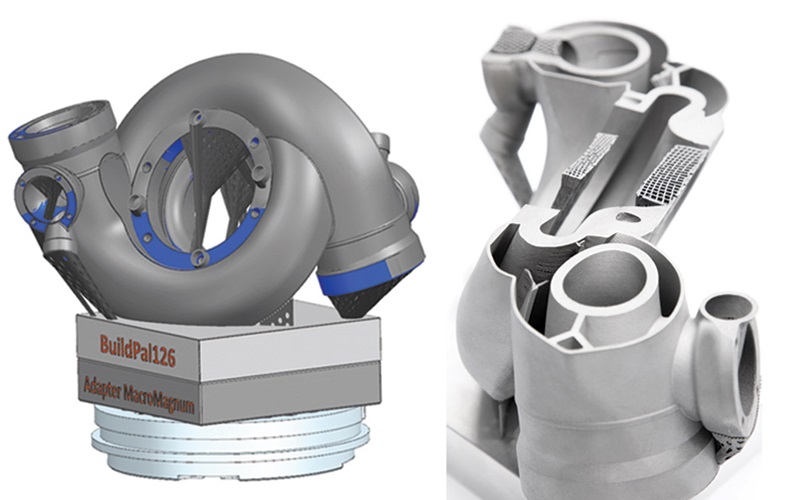
The part is a double-walled F1 turbocharger, made from a nickel-based heat resistant superalloy (Inconel LaserForm® Ni718 A) and manufactured using additive and subtractive processes. 

In Formula 1, double-walled turbochargers are needed to bypass turbo lag and increase efficiency, and thermal insulation is necessary for their effective operation. However, creating an air gap using a double-wall construction that prevents the heat within the core from reaching the outer shell can be tough to manage with casting, which falters with thin wall thicknesses.  

In short, for double-walled applications, metal casting is not an option for producing the basic shape, which is why GF Casting Solutions turned to its sister company, GF Machining Solutions, to make the part using an additive process.
With the help of m&h LS-R-4.8 laser scanning solution, GF Machining captures 3D data within the machine tool clamping.
Figure 1. With the help of Hexagon’s m&h LS-R-4.8 laser scanning solution, GF Machining captures 3D data about the shape and position of the printed surface within the machine tool clamping.


GF experts performed the 3D printing using an in-house DMP Flex/Factory 350 machine, which ensures efficient production of very dense, pure metal parts and, with high throughput and repeatability, can produce high-quality precision parts. Including preparation, it took over 55 hours to complete the finished blank part – a time which gives a strong hint at its high cost.

After printing, critical part features were checked for dimensional accuracy on a Hexagon Leitz Reference CMM, including individual points, angles, inside and outside diameters, and widths of the turbocharger. These measurements identified deviations from the nominal condition of up to 1 mm, which can occur naturally due to the thermal process of powder melting and are considered normal for functional surfaces in 3D printing. 


Reference points – a challenge when transitioning between manufacturing steps

The turbocharger has various functional surfaces and complex internal features (connecting elements) that needed to be precisely milled in post-build machining with a dimensional accuracy of maximum ± 0.01 mm compared to the CAD file. Machining could only occur after accurate reference points on the part had first been established.

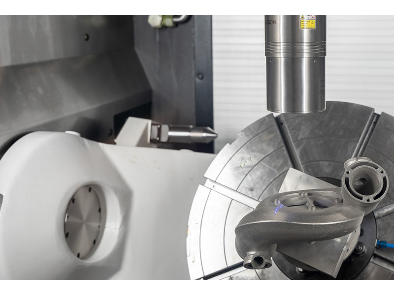
The clamping of parts on a machine tool is typically aligned to ensure the surfaces to be milled can be reached as easily as possible. On a 3D printer, however, the part’s orientation can be entirely different to ensure each element can be printed efficiently. In addition, there are distortions in the part due to the printing process itself. As mentioned, this was a factor with the turbocharger as well.
Point cloud displayed in HxGN NC Measure measuring software.
Figure 2. Point cloud displayed in HxGN NC Measure measuring software.
Individual measurement points extracted from the point cloud before Best-Fit alignment.
Figure 3. Individual measurement points extracted from the point cloud before Best-Fit alignment.

Individual measurement points after Best-Fit alignment.
Figure 4. Individual measurement points after Best-Fit alignment.

GF prepared and performed the 3D printing using the CAD file of the raw part as a basis. But this was done without knowing the exact future clamping position and orientation in the machine tool to be used for subsequent milling. 
In addition, to achieve the best printing results, the original CAD file had to be adjusted using specialised software. This included modifying the reference of the workpiece zero point and allowances for functional surfaces and contour supports. However, these modifications meant that even if this data could be reissued as STL data, it would no longer be compatible with the original CAD data in terms of reference points and surfaces.

Since no updated CAD file was available from the 3D print, this meant a rough alignment had to first be carried out on the milling machine, which takes a few hours using conventional tactile methods.
 
“3D printing is a holistic digital process, from design to the printed part. Extremely complicated parts can be produced. Today’s subtractive manufacturing, such as milling, is also high-tech, digital and, above all, automated,” explained Roland Zaugg, workflow expert at GFMS. “But in the transition from 3D printing to milling, sometimes you feel like you’re back in the 80s.” 

He wanted to close this gap by performing the alignment of the turbocharger on their milling machine much faster and, if possible, in the best case, to digitise the entire part as well. During his research, Hexagon introduced him to its complete machine tool laser scanning solution.

The m&h RC-R-100 radio receiver, which was already installed in GF’s CNC machine, can not only communicate with conventional probes, but also supports laser scanning with Hexagon’s wireless laser scanner for machine tools, the m&h LS-R-4.8. This metrology-grade sensor uses laser triangulation to capture 3D point clouds and area data of the entire surface of a workpiece – a capability that previously existed only with the help of external measuring devices. With this scanner, users can quickly capture and analyse a complete, data-rich image of a part. These devices are paired with Hexagon’s HxGN NC Measure, the associated CAD-based software, which is used to perform and evaluate part measurements.

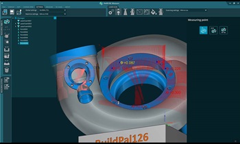
“This system was a revelation for us – we were now able to close the digital gap between these two manufacturing steps,” says Zaugg.
The difficult-to-manufacture Formula 1 turbocharger has extremely low tolerances and is complicated to measure.
Figure 5. The difficult-to-manufacture Formula 1 turbocharger has extremely low tolerances and is complicated to measure. Also, aligning the part in different situations between manufacturing steps can be challenging and time-consuming when using manual tools.
For rough alignment, the surface of the part was scanned. The resulting STL file was used in the CAD/CAM program to output an adjustment of the zero point. “This process took about 15 minutes, whereas in the first trial, with tactile measurement methods, it took around three hours,” says Zaugg. “Thus, in this initial alignment step there was already a 12-fold reduction in time needed.”

Another difficulty with 3D-printed parts is that, by their very nature, the functional surfaces cannot be used for precise alignment using a tactile probe. However, using 3D laser scanning, the complete surfaces can be used to determine if there is uniform oversize allowance across the entire part to achieve the best possible result before machining. 
Tool path programming in the CAM software is also challenging, which must consider the support contours after importing STL data and possible dimensional deviations of more than 1 mm compared to the original CAD/CAM data. “Such dimensional differences make planning milling paths difficult, which is why safety paths are often programmed to avoid a tool collision,” explains Zaugg. “In addition, tool wear is exceptionally high when milling Inconel alloy, another reason why it is so important for us to choose the most efficient milling paths possible.”

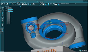
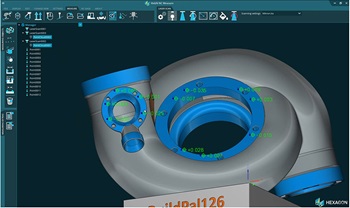
After another scan, the Best-Fit function of HxGN NC Measure determined the optimal displacement of the workpiece zero point and transferred this to the machine control.

Thanks to the known surface dimensions and the optimally selected zero point, GF could now precisely and efficiently mill the turbocharger’s functional surfaces and connecting elements. This final production phase was significantly shortened by using laser scanning to align and measure the part. And it also ensured there was enough allowance for further processing, preventing costly scrap from being produced.

Motorsports is all about speed. Achieving success in the realm of manufacturing for high-performance racing demands the perfect combination of digital solutions and production equipment to ensure rapid and cost-efficient production.
GF greatly reduced process times while ensuring accurate and reliable milling and fully digitised the turbocharger. With the help of Hexagon’s laser scanning solution, they bridged the technology gap between 3D printing and high-end milling manufacturing phases, creating a digital workflow that’s at home in the 21st century.
3D point data captured helps operators understanding the dimensional accuracy and the exact postions of parts in the machine clamping.
Figure 6. 3D point data captured with the laser scanners helps operators understanding the dimensional accuracy and the exact postions of parts in the machine clamping.

Engineering Reality 2024 volume 1

Accelerate Smart Manufacturing