Embraer develops higher quality aircraft components and assemblies 3x faster
by Adriano Passini, Manufacturing Engineer, Tooling Engineering, Embraer S.A. and Renato Ghiro, Application Engineer, Hexagon’s Manufacturing Intelligence division
Engineering Reality 2023 volume 2 edition
Empowering Makers for an autonomous sustainable future
A global aerospace company headquartered in Brazil, Embraer designs, develops, manufactures, and markets aircraft and systems, providing customer after-sales service and support.
Since its founding in 1969, Embraer has delivered more than 8,000 aircraft. On average, every 10 seconds, an aircraft manufactured by Embraer takes off somewhere worldwide, transporting more than 145 million passengers a year. Embraer is the largest manufacturer of commercial jets with up to 150 seats and the leading exporter of high-value-added goods in Brazil.

Overly complex analysis software leads to frustration, and lack of design optimisation
In the manufacturing department at Embraer, the tooling group is responsible for designing and developing tools and fixtures used in manufacturing, assembly, and testing aircraft systems. The manufacturing processes in the aeronautics industry propose many challenges due to the need for flight hardware to be lightweight and efficient. Parts and assemblies are expensive, and each design must meet high-dimensional tolerance standards but yet result in low mass. Thus, structural analysis is needed to ensure the design meets all the requirements before it is built. Their primary goal is to ensure that the tools and fixtures used in the production process are high quality, precise and reliable. This is critical in aircraft manufacturing to ensure aircraft systems’ safety, performance, and reliability.
Because many aircraft components must be lifted and turned during manufacturing, resulting in potential safety hazards, ergonomics must also be a priority to ensure good work conditions for the workers on the shop floor. And so, aircraft wings, fuselages, vertical and horizontal stabilisers, and flight control components must be designed with the tooling in mind. Safety is paramount, and Tool Engineering is responsible for precisely simulating all parts providing an acceptable safety margin before anything is built. Structural analysis is needed to ensure that the design meets all the requirements before a build can occur and to develop tooling structures that are as lightweight as possible. This trade-off often requires several iterations.
Embraer’s engineering team previously endured an incredibly complicated and time-consuming model-building experience to analyse the tooling structures. This excessive time the team spent modelling and meshing took away from the time they would have spent making design iterations. This led to design decisions with overly conservative safety margins, yielding heavier structures and non-optimal designs.
“MSC Apex has improved the quality and decreased the time of all the analyses compared with the previous CAE software. With the same number of engineers, we can deliver more results than before.”
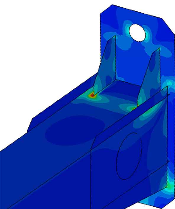
Figure 2. Lifting device von Mises tension.
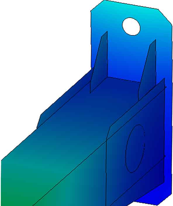
Figure 3. Lifting device translational displacements.
Embraer saw a boost in efficiency and speed without jeopardising quality
Embraer realised that to address this issue they needed a streamlined solution that met their needs. The new solution had to address clean-up, and enable a modern, more appropriate mixed mesh element types to suit the geometry. For finite element analyses within highly elastic and plastic structural domains, hexahedral meshes have historically offered some benefits over other finite element meshes in terms of reduced error, smaller element counts, and improved reliability. However, hexahedral finite element mesh generation continues to be difficult to perform and automate, with hexahedral mesh generation taking several orders of magnitude longer than current other mesh generators to complete. When evaluating new solutions, they implemented the hexahedral meshing technique in MSC Apex, which effortlessly yielded a much higher-quality mesh. Engineering teams could complete the meshing task three times faster than before.“The first time I used MSC Apex, I realised it was efficient and useful based on the time I saved. Midsurfacing and surface meshing in MSC Apex gave an excellent result. Some geometry cleanup and corrections were needed, but these tasks were easy due to tools like Defeature and Vertex/ Edge Drag,” explained Adriano Passini, Manufacturing Engineer at Embraer.
He continues, “The connections MSC Apex automatically created between different surfaces gave me more confidence. The methodology of evaluating the mesh with different kinds of parameters was the confirmation of a good job. The results in post-processing were even better. The animation of the simulation makes it easy to understand the direction and the intensity of displacements, and even helped to explain the results better to the engineers and managers involved in the design.”
Most of the shop floors at Embraer facilities are not climatised, and the temperature difference between winter and summer can range from as low as 10°C to as high as 30°C (50-90°F). Depending on some parts’ dimensional requirements, simulating the tooling’s thermal expansion is critical to ensure manufacturing precision. Further, the aircraft component is placed in an autoclave along with the tooling for manufacturing composite parts. The temperature inside can reach 180°C of range (356°F), causing thermal expansion in the tooling.
MSC Apex can perform analysis to study the thermal behaviour of a tooling device, allowing the effect of temperature to be predictable for manufacturing engineers. At
Embraer, engineers needed to easily apply these two loading conditions to understand the direction of tooling thermal expansion and stresses. Doing so allowed them to choose the best design and material for these structures.
Embraer engineers could easily export models prepared in MSC Apex to Marc to model the composite material’s curing. Modelling in Marc allowed engineers to build confidence in the manufacturing process and predict the time needed in the autoclave, thereby avoiding trial and error.
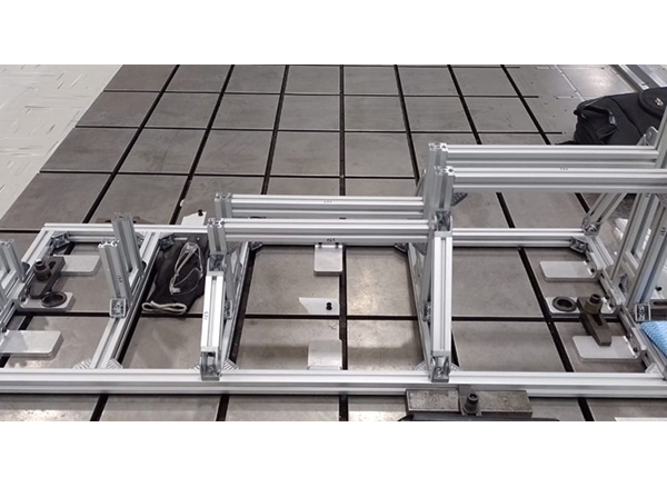

Figure 4. Modular aluminum structure.

Figure 5. Stress in the modular aluminum structure.
Engineering tasks completed three times faster
After switching to a solution that provided a unified environment for linear, nonlinear, and thermal analysis, Embraer’s engineers could complete their work three times faster than previously possible.
“MSC Apex has improved the quality and decreased the time of all the analyses compared with the previous CAE software. With the same number of engineers, we can deliver more results than before,” Passini explains. “Furthermore, the MSC support team added more efficiency because of how fast they gave us answers when we needed them. We plan to expand MSC Apex utilisation for more applications to reduce even more costs and time in engineering simulations.”
Faster and more efficient without compromise
The new modelling environment allows Embraer’s engineers to perform tasks three times faster than its previous software package. Its engineers no longer have to approximate structural models, leading to efficient parts, and Embraer can now perform efficient tooling analysis for metallic and composite components. The aeronautics manufacturer has increased speed, accuracy, and efficiency without compromising ergonomics or safety.

Figure 6. Displacements in the modular aluminum structure.