Department of Industrial Engineering - University of Padova
Author: Alberto Trevisan
Supervisor: Prof. Matteo Massaro
Course: Modelling and simulation of mechanical systems
In full-scale helicopters the primary stabilizing method, in most cases the only one, is the aero-elastic flapping of the rotor blades due to its high mass and slow response. In model helicopters the stabilization method used is the flapping of the flybar, which is an aerodynamically damped gyroscope device used to increase the stability of the vehicle in the pitch and roll axes and assists in its actuation. This device is well spread in robot helicopters because their small size causes an inherent instability and a fast time-domain response. In model helicopters this is also the only damping mechanism because their rotor hub is hingeless (rigid), so the blades can’t move upwards and they are too stiff to flap significantly. This hingeless system is adopted to decrease the control time and give a better sensation of control to the pilot, otherwise in full scale helicopters the blades are free to flap, or springs are mounted on the rotor to increase the stability of the system. This system increases the time that the helicopter needs to respond to the control inputs. The flybar system permits also to reduce the forces that the actuators must apply to control the rotor. The first design of this system came in the 50’s for full-scale helicopters and it used the gyroscopic effect of a bar with weights to regulate the tilt angle of the blades. To reduce the flapping motion of this mechanism was used a separate damper, this is the so-called Bell stabilizing system. Lately an airfoil replaced the damper and weights to generate the Hiller system. The modern design is called Bell-Hiller flybar mixer because puts together some design aspects of both the configurations.
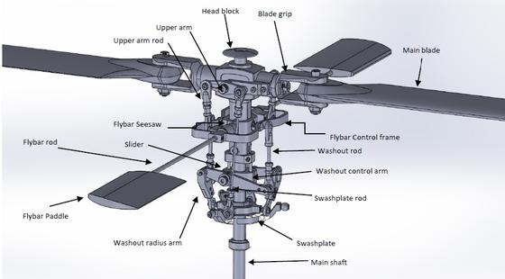
Fig. 1 – Mechanism description
The main simulations carried out can be divided in:
Kinematic analysis
- Blades and flybar roll e pitch angle variation for collective pitch in static conditions
- Blades and flybar roll e pitch angle variation for cyclic pitch in static conditions
Dynamic analysis
- Destabilizing torque on the swashplate
- Destabilizing torque on the Blade carriers
- Change in cyclic input tilt (stepped function)
- Identify the natural frequencies of the system in the linearized configuration of the rotating frame.
Optimization
- Minimum peak acceleration on blades for destabilizing torque on blades
- Minimum time to equilibrium for destabilizing torque on blades
Flexible bodies
- Simulation in hovering flight without the presence of lift forces and the blades modelled with flexible bodies, using as an input only the cyclic pitch.
- Simulation in hovering flight with the presence of lift forces and the blades modelled with flexible bodies, using as an input only the cyclic pitch. This simulation has been made to assess the effect of the lift force on the blades as a source of destabilization.
- Complete simulation with as input cyclic and collective pitch.
A conclusive simulation is here presented where the mechanism is both subjected to a cyclic input (i.e. swashplate tilt) combined with collective pitch (i.e. swashplate translation)
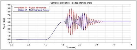
Fig. 2 – Comparison of the blades pitching angles during the complete simulation
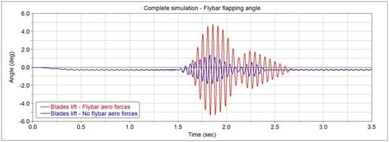
Fig. 3 – Fybar flapping angles comparison
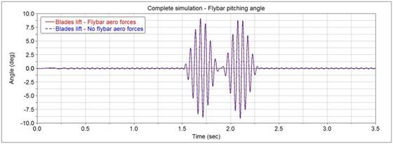
Fig. 4 – Comparison of the flybar pitching angles
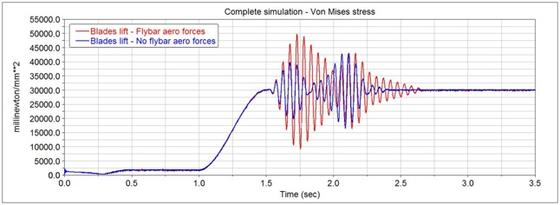
Fig. 5 – Higest point of Von Mises stresses on the blades
From the first kinematic analysis, the relation between the input, seen as the translation and rotation of the swashplate, and the output of the blades rotation and paddles pitch, for this mechanism, was found. This result is important to assess the differences between the static value that a quantity has and its values influenced by the dynamics of the mechanism, mainly by the flybar effect.
The flybar acts as a stabilizer considering the flybar pitch itself, lowering the output peak and damping the system when an impulsive external torque subjects the cyclic input, representing an external disturbance. This response generates a flapping motion in the flybar, which is the main characteristic of the flybar, that also affects the blades pitch since they are connected to the flybar seesaw. Considering an external disturbance, for example a lateral wind gust that runs over the helicopter, represented by two impulsive torques on the blades, the flybar reacts with the gyroscopic effect, maintaining aligned the blades plane with the flybar’s one. Therefore, the output, as a variation of blades pitch, is much smaller than without the flybar and this effect is not influenced by the presence of the Hiller input with the aerodynamic forces on the paddles, so the same response is present both in the Bell mechanism and in Bell-Hiller configuration. The overall effect can be summarized qualitatively saying that the mechanism presents a maximum blade pitch lower than ten times the one without the flybar.
The Bell-Hiller stabilizer acts slowing the response of the system subjected to a fast change in the cyclic input, since it is not affected by the collective pitch, and altering the response between input and output. This is due to the flapping motion that the aerodynamic forces induce on the flybar that alters the response of the system. The flybar pitch is not altered by the presence or not of the aerodynamic forces. The aerodynamic forces also act varying the force that the actuators must exert on the system to make it change configuration, in some cases changing the sign of it from pulling to pushing and making a more balanced system considering the whole period from the point of view of the power that must be exerted.
The paddles configuration used by the producers, where some additional masses are added to the plastic paddles finds its reason in the fact that the optimum configuration (considering as reference test the destabilizing torques on the blades) in terms of reduced initial acceleration peak to the blades compared to the paddles mass, is the one with a mass double than the one with the whole paddle in plastic (ABS). Therefore, considering paddle’s mass and blades peak angular acceleration, the better configuration is the one before mentioned. The same tendency is not found in the time to equilibrium which is quite the same changing the paddles mass and the equivalent damping coefficients.
Using a flexible bodies simulation, was found that the flapping and torsional compliance does not gives an additional damping in this type of helicopters since the blades are much stiffer than the ones in real helicopters so the blades flapping motion has a negligible influence on the mechanism.
Adding the aerodynamic forces to the blades and using the flexible bodies simulation, we have come to the result that the forces on the blades has a destabilizing influence as the flapping motion of the flybar since blades pitch is linked to the latter, but with much lower magnitude. We also measured the stresses on the blades at the chosen rotational speed caused only by the cyclic pitch and without the presence of the aerodynamic forces on the paddles.
To make an overall check of the stresses on the blades and the mechanism responses a complete simulation was performed considering the presence of the aerodynamic forces on the paddles and the combined effect of collective and cyclic pitch. The effect of the flybar seen on the rigid body simulation and the destabilizing effect caused by the blades aerodynamic forces are both present. Thus, the system presents a similar response as in the rigid body simulation but obviously a little more destabilized because of the combined presence of the aerodynamic forces. The main result of this simulation was the fact that the material chosen for the blades is not suitable for this application in terms of strength. Therefore, a carbon-epoxy blades or at least glass-epoxy must be adopted as done by the producers.