Technological development has made it possible to delegate to robots many activities that are too risky and too strenuous for humans. One of the areas where robots have repeatedly saved people's lives is that of bomb removal and the robots used in such operations are known as EODs (Explosive Ordnance Disposal).
The present work analyses, models and simulates by the way of the software ADAMS and Matlab the behaviour of Demine, the EOD robot manufactured by the company Robotec - lifesaving robotics, in order to identify its performances and to optimise them.
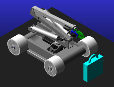
Initially, the CAD model of the robot was imported into ADAMS Modeler in order to Merge all the bodies that are part of the same assembly and don’t have relative motion between them and to apply constraints. In addition, the original locomotion system, consisting of 6 tracks, was replaced with a simpler one consisting of 4 wheels with a diameter of 80 mm. The refined model, shown in Figure 1, is composed of 5 sub-assemblies:
- Base: where the brushless motors and transmission systems for moving the wheels and rotating the Arm are situated. The robot frame is also present.
- Arm: it is composed of 3 aluminium mechanical links driven by two brushed linear electric actuators. It has 4 DOFs and it positions the Gripper.
- Gripper: this is the end part of the robot, known as the end effector and it is driven by a brushed motor. It is used to grasp the bomb by way of the synchronized movement of the flanges modelled using the Join:Gear function of Couplers.
- Right/left transmission: transmits motion to the wheels on the right/left side of the robot by way of a system of belts and pulleys made using the components of the Machinery/Belt Plugin.

The bomb, shown in Figure 1, was modelled by connecting a box to a torus and weighs 4 kg. In order to allow the robot interaction with the surrounding environment, Contact Forces were modelled: they act between the wheels and the ground, the claws of the Gripper assembly and the torus of the bomb, the ground and the bomb.
Initially, the direct and inverse kinematics has been studied by applying the Denavit-Hartenberg convention, focusing on the EOD manipulator. Subsequently, the trajectories that the two linear actuator of the manipulator has to follow to carry out the imposed tasks, formulated using the Chebyshev polynomials, have been optimised in order to reduce the overall energy that the two actuators have to spend. The optimization problem was solved in ADAMS by using the MMFD algorithm.
Then, the electric actuators and their controllers were modelled in Simulink obtaining the characteristic parameters from their datasheets. These outcomes have been imported into ADAMS through a .dll library to take into account the electro-mechanical behaviour of the actuators. The designed controllers are of two types: PI (Proportional Integral) and SMC (Sliding Mode Control). To obtain optimal performance from the second controller, a CAD-based approach was used in order to extrapolate, from the ADAMS environment, information regarding the dynamics of the linear actuator that moves the third link of the manipulator.
The flexibility of the manipulator third link was also considered in order to evaluate its deformations and stresses.
Ultimately, three different Simulations were carried out.
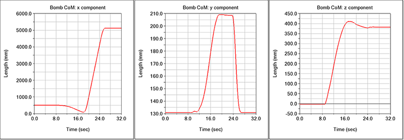
In Simulation 1, where the flexibility of the last link has been neglected, all motors are controlled by the PI system. This Simulation shows that the robot is able to perform the steps necessary for the removal of the bomb whose coordinates of the centre of mass, evaluated with respect to the global reference frame are shown in Figure 2. The x component relates to the distance travelled by the robot during transport phase, while the y component is linked to the lifting phase. Ultimately, the z component is related to the rotation of the Arm, which moves the bomb to the side during the transport phase.

Simulation 1 also shows that the voltage and current profiles required by the motors used are acceptable: they never exceed the maximum values shown in the datasheets and do not exhibit peaks or oscillations that could damage electrical and mechanical components.
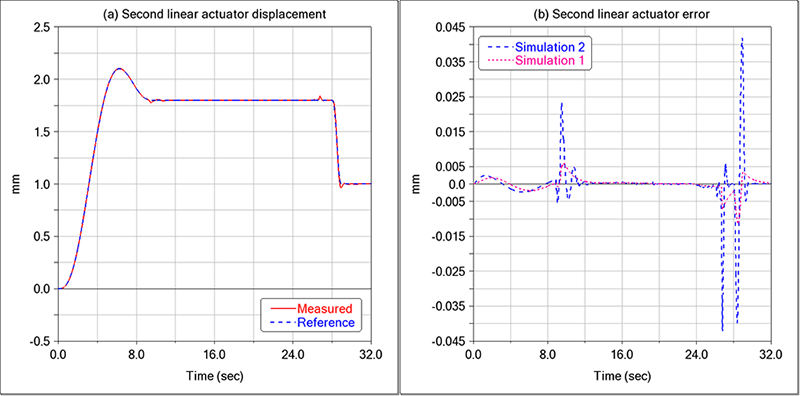
In Simulation 2, the flexibility of the third link is taken into account without changing the type of control systems. Simulation 2 showed that the control system of the second linear actuator used in Simulation 1 is not robust: it is not able to control the system after the introduction of third link flexibility. Therefore, it is necessary to reduce its proportional gain in order to obtain a more robust controller but with less precision, as shown in Figure 3.

Simulation 2 also allows us to evaluate what the stress distribution of the third link is, demonstrating that the robot operates in safe conditions with a 4 kg handled load: Figure 4.a and Figure 4.b show the moment in which the maximum deformation and stress are reached.

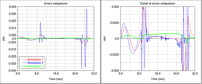
In Simulation 3 the PI controller of the second linear actuator is replaced with SMC. The application of this controller is more burdening from the implementation point of view, because it requires greater knowledge of the model which can be obtained through the CAD-Based approach. The controller, as shown in Figure 5, guarantees a lower maximum error than those achieved in both previous Simulations. Moreover, the use of the sat function guarantees the absence of the chattering phenomenon, allowing the SMC controller to be used without damaging the mechanical components on which it acts.

Autore: Giuseppe Ventura
Univeristà: Università degli Studi di Salerno
Anno Accademico: 2020/2021
Relatore: Adolfo Senatore