The main objective of the thesis is to create a robotic interface for production process in the industry. Robots are designed to transport materials and perform a variety of different tasks in production and industrial sites, optimizing the working environment and increasing worker safety. Industrial robots have the potential to significantly improve product quality. On each activity, applications are carried out with accuracy and high level of reproducibility, Figure 1.
Today’s industrial robots work in a wide range of industries, from semiconductors and automobiles to plastics processing and metal forging, increasing speed for manufacturing processes, operating 24/7. Three types of robots are considered, namely anthropomorphic, SCARA and Cartesian robot, as it is shown in Figure 2.
Cartesian robots are industrial manipulators that operate on three linear axes using a Cartesian Coordinate System (X, Y, Z).

They move in straight lines on three axes providing configuration flexibility, which allows users to modify the robot's speed, accuracy, stroke length, and size. Cartesian robots are one of the most prevalent forms of industrial robots, and they are frequently used in CNC machines and 3D printing.
SCARA (Selective Compliance Assembly Robot Arm or Selective Compliance Articulated Robot Arm) is a type of industrial robot, which moves an arm in the horizontal plane having an additional vertical axis. SCARA robots are typically used for assembly and palletizing, as well as biomedical applications.
An anthropomorphic robot is a robot with revolute joints. The mechanical movements and arrangement of an articulated robot closely mimics that of a human arm. They can range from simple two-jointed structures to systems with 10 or more interacting joints and materials. The majority of articulated robots have four or six axes. Assembly, welding, material handling, and packaging are common uses.
The Toolkit allows users creating the robot as well as deleting it, with user-friendly experience by giving access to modify the bodies, choosing the motion, setting the analysis, visualizing the results for all the three types of robots. This Robot toolkit helps to create a working robotic environment of multiple robots. From each one, there will be specific inverse kinematic analysis, direct kinematic analysis, and dynamic analysis. Bushing effect will be included in this toolkit. For the analysis, there will be specified results, which will be displayed as plots and the user can easily review them. For all the analysis there will be specified animation as user can play to verify or to understand process of the robot.
A robot's kinematic structure is described by a set of links, considered to be rigid bodies, and joints connecting them and constraining their relative movement, for example, revolute or prismatic joints. A robot's layout, at some instant in time, can be described by one of two methods:
- A list of coordinates for each joint (typically an angle or distance) expressed relative to some reference frame, aka zero position.
- A spatial representation of its links in the 2D or 3D world in which it operates, e.g., matrices describing the frame of each link relative to some world coordinate system.
The list of joint coordinates is known as the configuration of the robot: it is a non-redundant, minimal representation of the robot's layout. Direct Kinematics and Inverse Kinematics in robotics movement refer to calculate the relations between joint angles and end-effector DOFs. For direct kinematics, the joint angles are the inputs, the outputs would be the coordinates of the end-effector. For inverse kinematics, the given inputs are the coordinates of the end-effectors, the outputs to calculate are the joint angles (Figure 3).
Robot dynamics is concerned with the relationship between the forces acting on a robot mechanism and the accelerations they produce.
 Figure 3. Inverse and Direct kinematic in robot
Direct dynamics is mainly used for simulating performances, vibrations, precision. Inverse dynamics is used for on-line control of robot motions and forces, trajectory design and optimization, design of robot mechanisms, and as a component in some forward-dynamics algorithms It becomes fundamental inertia parameters identification.
Robot toolkit is a customized development of Adams View, which helps to create a specified environment for performing automatic modelization and analysis of robot .It is built using command files, macros, dboxes, and ribbons, together with fully parameterized robot models.
Macro is a programming feature with which the Adams View commands are executed in a user-defined manner. The commands of macro are executed using the Adams View command language. Using the parameters, data are sent to the macro to execute it when needed. They act as a placeholder for information and provide the required information during the execution time. Instead of manually change data of the robot, run analysis and manage results, parameterization (points, design variables, functions), and tools (DS, DOE, OPT) into Adams View provides to automate every change. Using parametric analyses, a series of simulations is automatically performed helping the investigation of the influence of design variables on model performance:
- Design study, which shows the effects of varying one design variable.
- Design of Experiments (DOE), which shows the effects of varying several design variables simultaneously.
- Optimization, which adjusts design variables to minimize or maximize objectives of model.
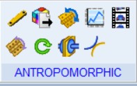 Figure 4. GUI customization
We can model three types of robot in the toolkit, defined by points, bodies, joints, motions, forces, bushings, measures.
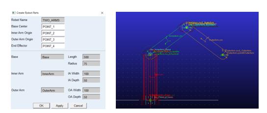
Motion are applied using
- Step Function
- Simple harmonic function
- Constant time.
For each function, there will be a specific formula applied on the motion of the robot.
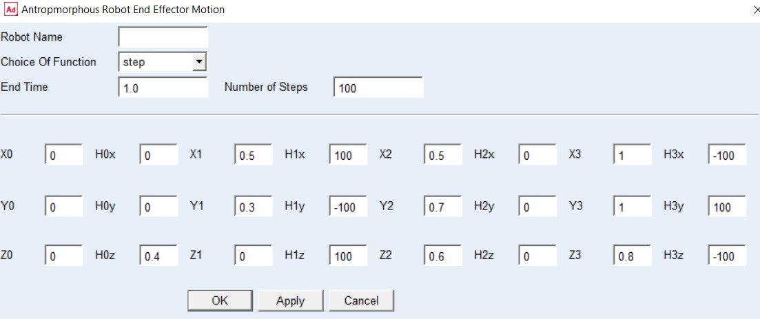 Figure 6: Motion on End Effector
During inverse kinematics analysis, angular rotation and relative angular velocity between bodies are measured, together with translational displacement X, Y, Z of the end effector. These measures will be saved and used for direct analysis, through spline creation in the Adams Postprocessor. These measures will be given as an input to perform direct kinematics.
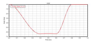 Figure 7: Spline creation from measure of angle
From the direct kinematic analysis, evaluation of torque measure will be taken as input.
By the postprocessor, this measure is converted into the spline and then be applied as forces to the robot to perform the dynamics.
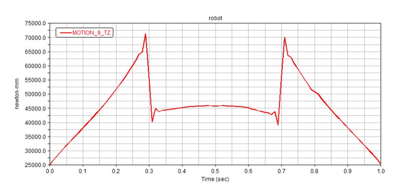 Figure 8: Spline creation from measure of torque
After dynamic analysis verification, the model can be modified including compliances, using Bushing, a linear flexible connection, which allows small translational and rotational relative displacement between bodies: a flexible revolute connection is modelled with 5 high constant stiffness and damping values along X, Y, Z and around X, Y axis, and putting 0 around relative Z Axis.
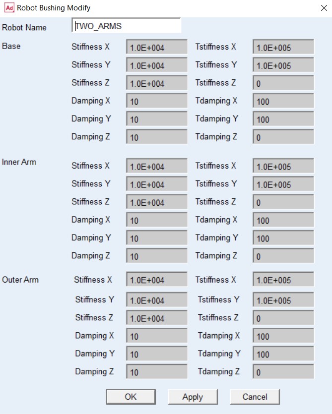 Figure 9: Bushing data
| Tutors: | Student: |
|---|---|
| Prof. Erika Ottaviano | Bhuvanesh Sudarsanan |
| Daniele Catelani (Hexagon) |
Anno Accademico 2021/2022