Introduction
The present work proposes a new numerical technique for the integration of supersonic flows over movable walls, to simulate the flow conditions generated over thermal shields made of inflatable materials (figure 1), which are typically used for aerocapture or re-entry planetary manoeuvres.
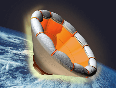
This technique considers the mutual interaction between the fluid dynamic field and the deformation of the flexible aeroshell. The movable wall is treated as a discontinuity in the flow field, relying on the recently released code UnDiFi-2D [1] for the fitting of fluid dynamic discontinuities. This code works coupled with the Computational Fluid Dynamic (CFD) solver EulFS [2], allowing the integration of Euler's equation in two-dimensional unstructured (2D) grids. The coupling between the wall deformation and the distribution of the flow variables has been achieved by implementing a new UnDiFi-2D's algorithm, capable to handle the presence of non-rigid boundaries which can modify their geometry (movable walls). This new algorithm imports the CFD solution of the flow field into the finite element analysis solver MSC-Nastran, which calculates the new wall configuration depending on the wall materials, inflation pressure, and wall pressure due to the external flow. In particular, the wall is allowed to move over and independently of the background mesh, which is locally adapted at each time step to ensure that the nodes and the edges that make up the discontinuity are part of the triangular grid that covers the entire computational domain.
From the structural point of view, the wall under examination is treated as a membrane: membranes are thin, bi-dimensional structures in three-dimensional space that exhibit a negligible bending stiffness due to their reduced thickness, and a load repartition in the membranal direction. The Nastran element that best summarizes the characteristics of the membrane is the PSHELL element, which defines the membrane, bending, transverse shear, and coupling properties of thin shell elements. To couple the internal stress state of the material with the applied loads, it is necessary to consider the “load history”, thus carrying out a non-linear analysis, which is performed via the Nastran Sol400 solver.
Test model: the inflatable circular cylinder
Considering a hypersonic flow over a cylinder as in figure 2(a). Due to the blunt shape of the wall, a bow shock will form in front of the body, giving rise to a variable pressure distribution over its surface, which gradually reduces moving along the wall starting from its maximum value at the stagnation point (on the symmetry axis). Supposing that the cylinder is of inflatable material, its shape is maintained by an internal pressurizing gas that contrasts the external pressure generated by the flow.
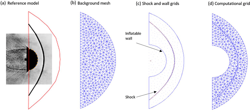
The computational domain (figure 2d) is obtained via a re-meshing of the background mesh (figure 2b), which includes the points of the wall and the shock (figure 2c); note that the wall becomes an external boundary for the computational domain.
Purely structural analysis
A purely structural non-linear analysis has been conducted to find the thickness and the stiffness values which allow determining the operative limits of our membrane. Three types of materials have been investigated; their properties are similar to models for inflatable thermal shield application. These materials have been loaded with different internal pressure levels, and with an external pressure distribution (figure 3), trying to determine:
- the internal pressure which guarantees the shape stability under an asymmetrical external pressure load.
- the minimum internal pressure required to sustain the external pressure load.
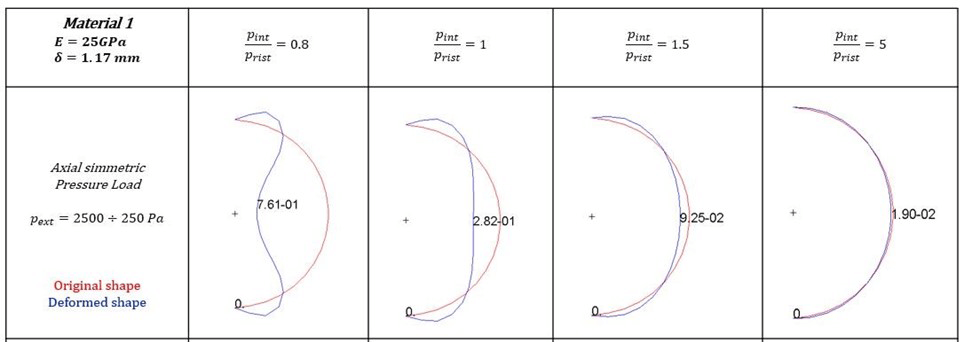
The best performing material has a Young modulus E=25 GPa and a thickness of 1.17 mm. This analysis evidences the importance of the internal pressure level to control the shape of the inflatable wall. The ratio between the internal and the external pressure must be greater than 1.3 to ensure structural stability but still have an appreciable deformation, while pressure ratio values equal to 5 are sufficient to stiffen enough the wall, maintaining its circular shape.
Coupled analysis results
Figure 4 shows the capabilities of this new developed procedure, integrating a hypersonic flow at Mach=20 over an inflatable circular cylinder with the same structural properties of the purely structural analysis. The internal pressure level for this simulation is set equal to pint/prist =1.5 (where p_int is the internal inflation pressure, which is kept fixed, and p_rist is the stagnation pressure, which is the maximum value of the pressure acting on the wall).
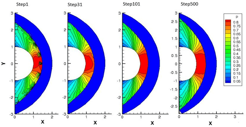
Note that the initial solution at the first-time step is obtained by a shock-capturing simulation. In this first iterative solution, the fluid field is not uniform and is characterized by strong spurious disturbances due to the shock-capturing process affecting the shock layer region. The fitting algorithm progressively eliminates all these disturbances, leading to a quite clean flow field in the last integration step. At the 500th integration step, both the wall and the flow reach stationary conditions, providing a wall shape different from the original circular cylinder.
The changes in the wall shape, in the shock position, and in the computational mesh are highlighted in figure 5.
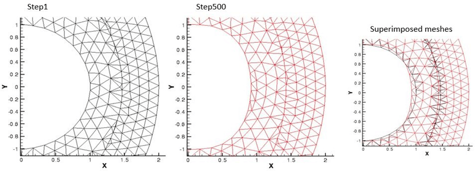
Superimposing the two meshes is quite clear how the solver handles the deformation of the wall, changing the computational mesh during the integration. As expected, the wall tends to be more flattened due to the difference between internal and external pressure.
Drag modulation control implementation
Finally, this coupling procedure was applied to the typical flow conditions of an aerocapture manoeuvre. To calculate the deformation of the inflatable wall along this trajectory, this analysis has been conducted for different values of internal pressure. Indeed, the wall shape caused by the internal pressure allows the implementation of a drag modulation control strategy, useful for compensating unpredictable atmospheric density variations in aerocapture or re-entry missions. Figure 6 highlights the effect of the internal pressure upon the stiffening of the inflatable wall: at the same pressure ratio, the Aerodynamic drag coefficient-CD increases with the stagnation pressure; this happens because the wall tends to flatten more. Increasing the level of internal pressure, the wall becomes more rigid, and its shape depends less on the external pressure.
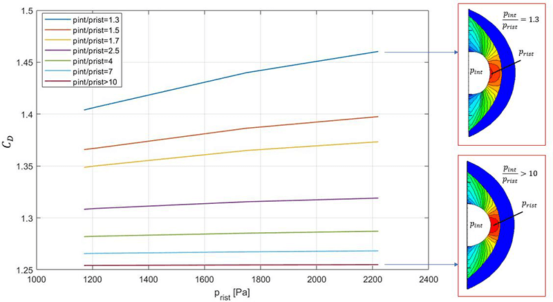
Finally, it is possible to elaborate a drag modulation strategy for the nominal aerocapture mission. In fact, the atmospheric braking due to the aerodynamic drag is:
D=1/2 ρ S CD V2
Where ρ is the atmospheric density, S is the cross-section area of the vehicle, CD is the drag coefficient (which essentially depends on its shape), and V is the vehicle’s velocity. Setting a nominal trajectory with a certain atmospheric braking, regulating the internal pressure it is possible to vary the vehicle’s CD, allowing to compensate possible atmospheric density variations.
Concluding remarks
The circular inflatable cylinder as thermal shield showed in this work represents the benchmark model for this kind of coupled analysis, and it has been used to test the potentiality of this new procedure. It is worth remarking the high accuracy achieved by both the aerodynamic and the structural sides; in fact, the fluid dynamic solution reaches the stationary in just 500 iterations with a coarse mesh, while the structure requires only 5 integration steps to reach the final equilibrium shape. Indeed, this work lays the foundations for significantly more accurate future developments, such as the study of more complex configurations, or also the possibility to model the internal gas side. Further on, it may be possible to investigate over a strong coupling procedure able to consider transient behaviours for both the wall and the flow; allowing to analyze the deployment and instabilities of inflatable shields, with the aim of improving the feasibility studies over aerocapture or re-entry maneuvers.
Leonetti Emanuele, University of Rome “La Sapienza”