Design of an impedance control of a multi-arm space manipulator for capturing a non-cooperative target
Università degli Studi di Roma “La Sapienza”
In the near future robotic systems will be playing an increasingly important role in space applications such as repairing, refueling, re-orbiting spacecraft and cleaning up the increasing amount of space debris. In such missions, the control of contact forces between two bodies represents a big challenge for mission success, especially when autonomous robotic systems want to be employed. In fact the contact forces and, of course, the relative motion between two objects must be controlled carefully so to avoid unexpected collision and/or damage on the robotic systems, i.e. the chaser satellite and the target satellite as well. Space Manipulator Systems (SMSs) are robotic systems made of a base platform equipped with one or more deployable arms. In the case study here presented, a simulation of a non-cooperative satellite capture mission performed by a two-arm SMS is considered (under the hypotheses of planar motion and rigid bodies). In particular, the pre-grasping phase is analyzed. The latter is characterized by the issue of maintaining a stable contact between the SMS terminal parts (i.e. the end-effectors) and the target satellite after their first contact has occurred (see Fig. 1).
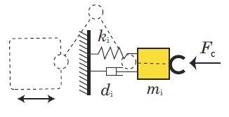
The Impedance Control approach is a suitable strategy to solve this problem. In this approach the end-effector is controlled in order to make it behave as if it was a mass-spring-damper system regardless of the reaction motion of the base so to absorb the impact energy (see Fig. 2).

Impedance Control concept for a space manipulator (H. Nakanishi, K. Yoshida, “Impedance control for free-flying space robots – basic equations and applications”)
Furthermore, since Impedance Control does not impose explicit requirements on the base motion, the latter can be separately controlled by means, for example, of a Proportional-Derivative (PD) Control. The complexity of the several aspects and requirements to be considered significantly limits the possible numerical codes to be used for the system dynamic simulation. The choice adopted in this study is to use the MSC.Adams software in co-simulation with an Impedance+PD Control scheme developed in the Simulink environment (CO-SIM). This allows to simulate in detail the kinematics and dynamics of the space robot and the target satellite and, of course, the contact dynamic phase. Fig. 3 shows a block diagram of the co-simulation logic. Furthermore, a simulation of the system dynamics including a simplified contact force model (MAT) is carried out as well in order to compare its results with the ones obtained from the co-simulation.
The target is considered to be approaching the SMS with a linear velocity of 5 cm/s and an angular velocity of 1 deg/s. As a result of the implementation of the above cited control strategy, the mission goal that wants to be achieved consists in keeping a stable contact between the two spacecraft after the first contact and bringing the initial linear and angular velocities of the target to zero in a fixed time (it is convenient to reduce the target initial velocities as close to zero as possible before proceeding with the successive grasping phase). The effectiveness of a control strategy in a pre-grasping operation can be positively evaluated when some requirements on the kinematic and dynamic state of the SMS and the target are verified (the adopted threshold values are reported within parentheses):
1. The absolute values of the contact forces components become sufficiently small (≤ 1 N);
2. During the maneuver the distances between the end-effectors and the target are null or within a prescribed tolerance (of the order of centimeters);
3. During the maneuver the SMS base shows relatively small linear and angular displacements components absolute values (respectively ≤ 5 cm and ≤ 2 deg);
4. The absolute values of the target linear and angular velocities components become smaller than prescribed design ones (respectively ≤ 0.5 cm/s and ≤ 0.05 deg/s);
5. Conditions 1 and 4 are maintained for a prescribed time interval (of the order of 10 s).
As regards the fifth requirement, it can be said that it is functional to the successive grasping phase in the sense that the prescribed time interval could be, for example, the time that is necessary to the grippers (or the robotic hands) to perform the grasping maneuver. In Fig. 4 the configurations assumed by the SMS and the target when the Impedance+PD Control algorithm is applied are shown. It is possible to observe that at the end of the maneuver both the end-effectors of the SMS remain very close to the target. From Fig. 4 to Fig. 10 it can be seen that the above mission requirements are satisfied and the differences highlighted by the comparison between CO-SIM and MAT results suggest that the co-simulation approach is the preferable methodology to be used.
Autore: Angelo Stolfi, Università degli Studi di Roma “La Sapienza”


