Active control of camber and toe angles to improve vehicle ride comfort
Università Federico II, Napoli
A vehicle suspension system provides a smoother ride on rough roads, at the same time ensures that the wheels remain in contact with the ground and that the rolling of the vehicle is reduced to a minimum. The suspension system includes three main parts: a structure that supports the weight of the vehicle and determines the geometry of the suspension, a spring that converts potential energy to kinematic energy or vice versa, and a shock absorber that is a mechanical device designed to dissipate the kinetic energy.
The functioning of a suspension is usually studied by motor vehicle engineers through three important principles:
- Ride Comfort: Ride comfort is defined based on how a passenger feels within a moving vehicle. Generally, ride quality can be quantified by the level of vibration.
- Road Holding: The forces on the contact point between a wheel and the road act on the vehicle body through the suspension system. The amount and direction of the forces determine the vehicle’s behaviour and performances.
- Handling: A good suspension system should ensure that the vehicle will be stable in every manoeuvre. The vehicle should respond to the driver’s inputs proportionally while smoothly following his steering/braking/accelerating commands.
The aim of the new suspension design is to improve ride comfort through active control of Camber and Toe angles.
A sports vehicle modelled in Adams Car has been used. The overall model (assembly) consists of the following subsystems:
- Front suspension
- Front steering
- Front wheel
- Real wheel
- Body
- Front antirollbar
- Rear antirollbar
- Brake system
- Front powertrain
- Rear suspension
The modified subsystem is the Rear suspension. The original rear suspension is a Trailing-arm suspension. The passive suspension system is shown in Fig. 1. This type of suspension is provided with an oscillating arm (magenta) that connects the wheel and the frame. It is arranged almost parallel to the direction of travel. The connection between wheel and frame is also allowed by the presence of two transverse arms, one rear (green) and one front (red). The spring supports the vehicle’s weight and makes a suspension tolerable for passengers. The shock absorber allows to dampen the impulses.
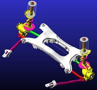
Fig. 1
The controlled variation of the Camber angles of the right and left rear wheels is allowed by the addition of two actuators positioned on the upper part of the Shock absorbers and orthogonally to the longitudinal direction of the vehicle (Fig. 2).
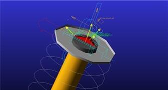
Fig. 2
The controlled variation of the Toe angles of the right and left rear wheels is possible thanks to the replacement of the rear arm with two links connected through a translational joint that allows the variation of their relative position. An actuator is positioned at the joint (Fig. 3).
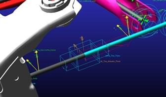
Fig. 3
The concept behind the Camber angle control system is the application of a force proportional to the difference between the reference and the actual Camber angle (Fig. 4). This force allows the wheel to rotate around an axis longitudinal to the vehicle until the desired position is reached. Similarly for the Toe angle.
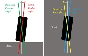
Fig. 4
Suspension Analysis (Fig. 5 – 6)
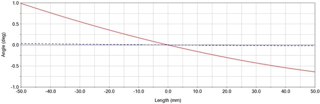
Fig. 5
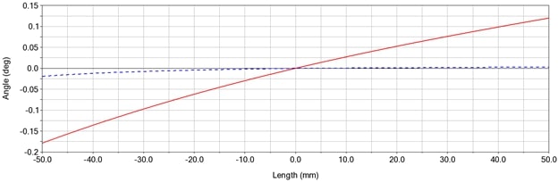
Fig. 6
The correct functioning of the system has been verified through a Suspension Analysis in Adams Car. The simulations carried out have been a parallel wheel travel and an opposite wheel travel.
Parallel wheel travel
A parallel wheel-travel analysis keeps the left wheel and right wheel heights equal, while moving the wheels through the specified bump and rebound travel. A 50 mm bump travel and -50 mm rebound travel have been set. Total wheel travel has been 100 mm. The reference angle chosen is equal to 0 degrees. Without control, the maximum angle value is 0.988 degrees. With control, the maximum angle value is 0.0363 degrees. The decrease is 96%. The same variations occur for symmetry also for the left wheel.
Opposite wheel travel
An opposite wheel-travel analysis moves the left and right wheel through equal, but opposite, vertical amounts of travel to simulate body roll. The left and right wheels move over the specified bound and rebound travel, 180 degrees out of phase with each other. A 50 mm bump travel and -50 mm rebound travel have been set. Total wheel travel has been 100 mm. Variations out of phase of 180 degrees have been found for the left wheel. The results are consistent with the independence between left and right wheels of this type of suspension.
Full-Vehicle Analysis
The modified suspension has been incorporated into the sports vehicle modelled in Adams Car.
During a turn, the vehicle rolls due to the forces of inertia. Since the x-y plane integral with the vehicle is rotated with respect to the horizontal, the arctangent of the ratio between the distance along z and along y of markers (a) and (b) does not define the angle of Camber, but the angle between the vertical axis of a wheel and the vertical axis of the vehicle.
The rear wheels also rotate together with the vehicle (Fig. 7 left). This leads to a decrease in the contact footprint. In order to obtain an improvement in performance in terms of comfort whatever the maneuver, it has been decided to adopt variable reference angles. The reference angle of the inner wheel with respect to the vertical to the vehicle is chosen positive and equal in absolute value to the roll angle. The reference angle of the outer wheel with respect to the vertical to the vehicle is chosen negative and equal in absolute value to the roll angle. In this way the wheels will approach the vertical position with respect to the road (Fig. 7 right) increasing the contact footprint.
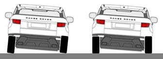
Fig. 7
When a turn is made, the inner wheel always makes a tighter curve than the outer one. With a zero Toe angle for the rear wheels, the tires are forced to make curves of the same radius. To improve the contact between the tire and the road, it has been decided to use an appropriate Toe angle (Fig. 8 right). This angle is applied only during a curve. The Toe angle is chosen positive and equal to 3 times the yaw rate in absolute value for the inner wheel. Negative and equal to 1.5 times the yaw rate in absolute value for the outer wheel.
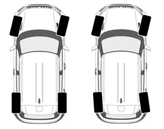
Fig. 8
In order to develop a control system with variable references, a cosimulation has been used between Adams Car and Simulink.
The manoeuvres carried out have been two variations of Constant Radius Cornering (Fig. 9 - 10), two variations of Fish-Hook (Fig. 11 - 12) and two variations of Swept-Sine Steer (Fig. 13 - 14).
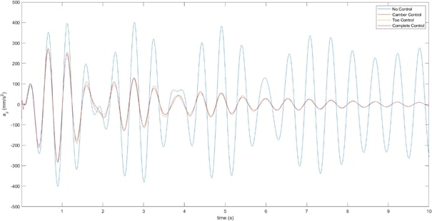
Fig. 9
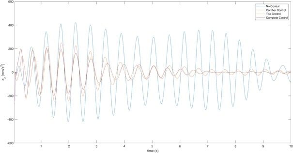
Fig. 10
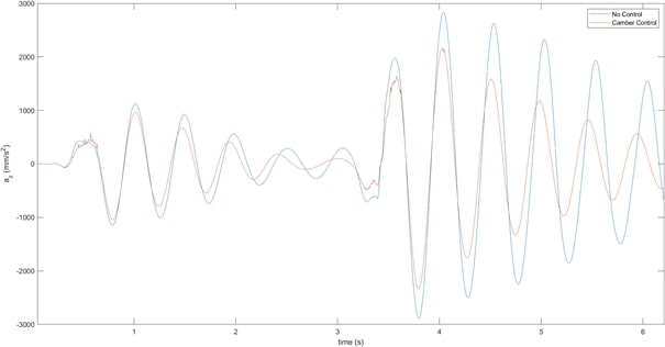
Fig. 11
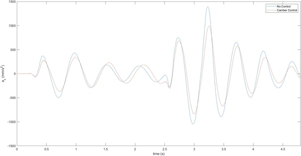
Fig. 12
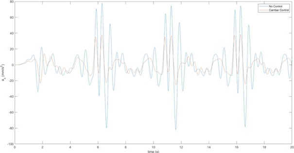
Fig. 13
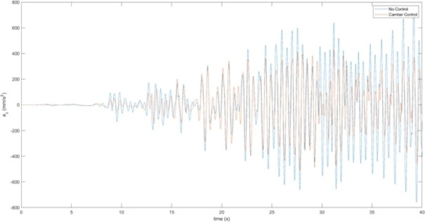
Fig. 14
A decrease in the vertical acceleration of the center of gravity has been achieved by controlling the Camber angle for maneuvers where a trajectory or rotation of the steering is imposed. The Toe angle control has allowed a decrease in vertical acceleration when a trajectory is imposed.
Autore: Raffaele Marotta