Use of advanced co-simulation tools for CFD-Multibody modeling and analysis of a Landing gear
Politecnico di Torino
The aim of this thesis is to analyse the advantages of the co-simulation performed with the software MSC CoSim: co-simulation allows to execute coupled analysis between software each of them specialized on simulating different physics, but able to communicate each other in order to get more realistic results. In the present work an aeronautical landing gear is analysed coupling the full dynamics through multibody (MSC Adams) and CFD analysis (MSC scFLOW).
Communication and exchange of physical quantities between two operative requires to build two different models with the right communication channels (marker/nodes, displacements/forces).
Adams Model
The landing gear model is defined by 8 parts joined through rigid connectors.
It is simulated the transition from a closed configuration to an extracted one with the use of a rotational motion law. Displacement of different parts are the quantities which the co-simulator gets from Adams and transfers to scFLOW which passes back aerodynamic forces defined in Adams as General Forces in the model, in particular on the parts considered immersed in the aerodynamic field and involved in the movement. The GForces are particular forces not filled by the user but by the co-simulator with the aerodynamic forces values obtained from CFD software.

Figure 1: Landing gear model
scFLOW Model
The CFD model is built starting from the Adams geometry imported in the pre-processor, but a preliminary phase (defeaturing) is applied to improve the CAD model and avoid issues during calculation phase. After this, to obtain moving parts the “Overset Mesh” feature is used: for each moving part a domain has been created.
Also setting of the solved equations and conditions is fundamental to get solution convergence and accuracy, as shown in the following table:
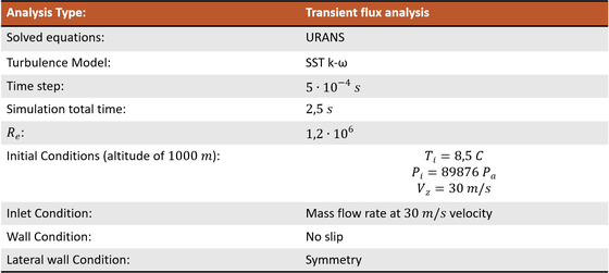
The calculation grids have been built by refining the areas of greatest interest, in particular the landing gear surfaces and the compartment wall area in which the boundary layer and its separation is significant.

Figure 2: Main Domain Mesh

Landing gear leg domain mesh
Coupled calculation and Result
After the completion of the model, the COsim engine runs driving analysis in both codes and managing the data exchange; at the end the results can be analyzed.
Landing gear extraction process, from the close position to the full opened.
The differences between the presented necessary torques in the two figures can be found considering the presence of the aerodynamic forces in the coupled case, in particular in the first moments of the simulation the force along z-axis contrasts the extraction of the landing gear pushing it inside the compartment while after about 1 second the force becomes positive and concordant with the landing gear extraction.

Comparison between the necessary torque in a coupled analysis on the left and an uncoupled on the right.

Calculated aerodynamic forces on the left and transferred ones on the right.
In conclusion the simulation has led to consistent results, however further investigations would be necessary.
The study of co-simulation could certainly lead to more accurate analyses in the future in which different physical phenomena can interact and be studied simultaneously.
The impact this tool have on the engineering industry can therefore be considered certainly positive, leading to results comparable to experimental tests with greater reliability.

Landing gear turbulent wake
Autore: Marco Carotenuto