Politecnico di Torino - Department of Mechanical and Aerospace – Team Policumbent

Air pollution, traffic jam and parking problems are increasing more day by day because of growing populations in the cities and rising number of motor vehicles. To avoid all of these, more small and more ecologically sustainable transportation solutions such as bicycle and velomobile can be preferred. Velomobiles are three-wheeled fully faired Human Powered Vehicle with a recumbent cycling position. In some circumstances they can be more attractive than bicycles as they allow higher speed, weather and crash protection and an extended travelling range. Also considering the high price of fuel it is a cheap mode of transport in this regard.
In this thesis, a three-wheeled velomobile for use in urban areas, which has a tadpole design (i.e., has two wheels in the front and one in the back), was introduced. Although they have some advantages such as having light and narrow design, they are not very stable in harsh maneuvers. Different methods have been proposed to improve their stability. Among all, applying camber angle to the wheels and tilting the body are the most promising approaches. Choosing between them, however, completely depends on the purpose of the vehicle. That is, for maneuvering and fast driving, usually tilting system is preferable, while for normal commuting in cities, cambering system is recommended. Because of that in this study, applying camber angle to front wheels was discussed. 
First mathematical model was built in Matlab in order to calculate the lateral acceleration threshold which causes the three-wheeled velomobile to roll over. In Matlab model the following parameters are kept constant and only camber angles applied to front wheels modified:
  • Vehicle mass
  • Wheelbase
  • Track
  • Tire radius
  • Cg position
  • Roll center position
  • Initial roll angle
  • Longitudinal acceleration
The outputs of the model are:
  • Lateral acceleration
Following results were obtained from Matlab simulations:

Camber Angle (degree)

Rollover Lateral Acceleration Threshold (g)

Difference According to +2.5° Camber Angle

+2.5

0.8802

0,00 %

0

0.9052

2,50 %

-2.5

0.9318

5,16 %

Table 1: The effect of applying different camber angles on front wheels
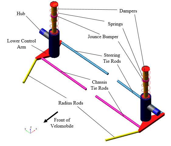
Later a multibody dynamic model were created in MSC Adams/Car in order to obtain more accurate results. The overall model is made up of various subsystems including:
  • Front suspension
  • Rear suspension
  • Steering
  • Body
  • Front wheel
  • Rear wheel
  • Powertrain 
 
A commercial suspension system was used for the front suspension of the velomobile. This commercial suspension system was similar to MacPherson suspension system which is used in road vehicles. Because of that the front suspension of the velomobile was derived from the existing MacPherson template in the shared database of Adams/Car and then the necessary modifications (like changing hardpoint locations and adding new parts like Chassis tie rod) are made.

figure1

Figure 1: Front Suspension

The rear suspension was designed as monoblade structure which provides the users easy maintenance. It consists of a trailing arm (link), spring-damper system and rear wheel axle.

figure2

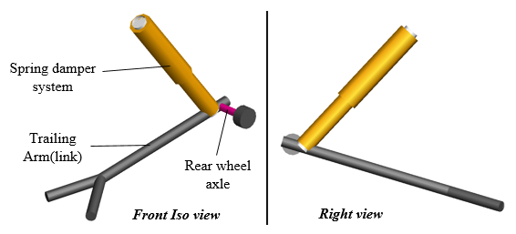
Figure 2: Rear Suspension


To design the steering system for the velomobile, the rack pinion steering template from <acar_shared> database was used firstly. By eliminating rack-pinion and housing part and adding Ackermann Part, velomobile’s steering system was obtained as shown below:

figure3

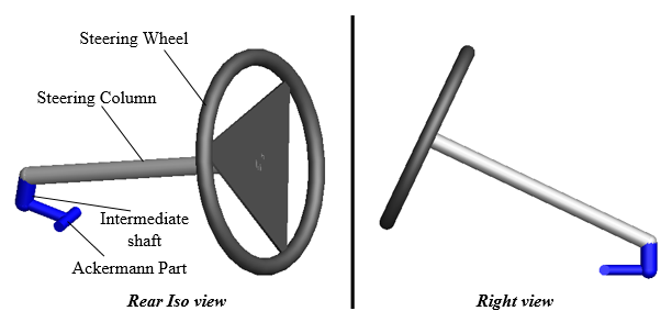
Figure 3: Steering System


During design phase first of all the maximum steering angle was determined by leaving sufficient width for cyclist’s legs and sufficient clearances for the movable parts in the front suspension.

figure4

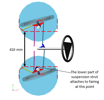
Figure 4: Lower part of the suspension strut attachment point


After modelling all subsystems, the full-vehicle assembly was created in order to analyze the slow-speed maneuverability of the velomobile and then Ackermann Part of steering system was modified until obtaining the desired turn radius (less than 4.5 meters). The aim of the modification of Ackermann part was reducing the Ackermann error.

figure5

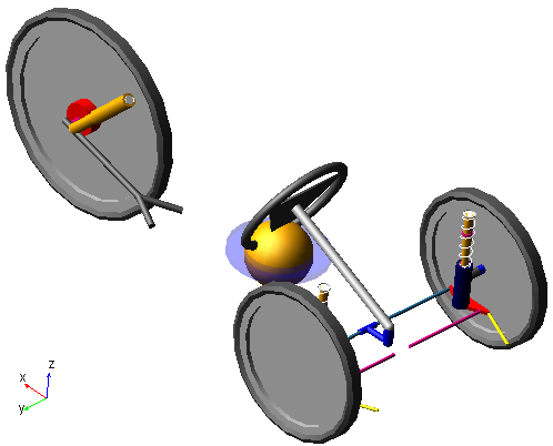
Figure 5: Full-Vehicle Assembly

figure6

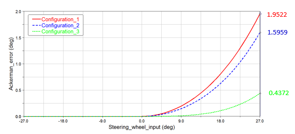
Figure 6: Steering wheel input vs. Ackermann error

Finally three different concerning maneuvers were simulated in order to better understand the rollover dynamics of the velomobile:


Constant Radius Cornering Analysis

Inputs of the model were:
  • Camber angle
  • Turn radius
  • Initial longitudinal velocity
  • Longitudinal acceleration
 
The outputs of the model were:
  • Rollover longitudinal velocity thresholds
  • Rollover lateral acceleration thresholds

figure7

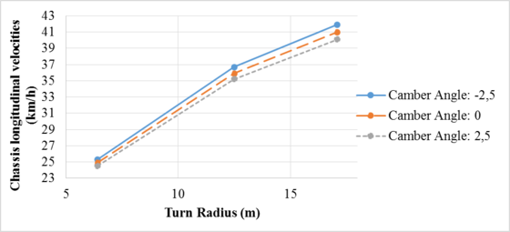
Figure 7: Turn radius vs. Longitudinal velocity threshold according to each camber angle

figure8

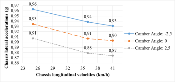
Figure 8: Camber angle vs. Rollover lateral acceleration threshold according to each turn radius

 
Ramp Steer Analysis
 
Inputs of the model were:
  • Camber angle
  • Initial steering angle
  • Steering angle rate
  • Longitudinal velocity
 
The outputs of the model were:
  • Rollover longitudinal velocity thresholds
  • Lateral acceleration
 
Step Steer Analysis
  • Inputs of the model were:
  • Camber angle
  • Initial steering wheel angle
  • Final steering wheel angle
  • Step duration
 
The outputs of the model were:
  • Rollover longitudinal velocity thresholds
  • Roll angle
  • Inner wheel normal force

figure9

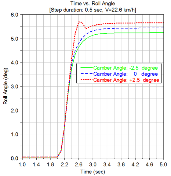
Figure 9: Roll angles at 22.6 km/h according to each camber angle

figure10

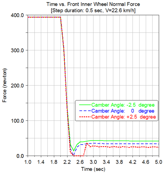
Figure 10: Front inner wheel force at 22.6 km/h according to each camber angle

 
Master of Science Thesis of: Refik Ahmet ÖZDEMIR
Academic Advisors: Prof. Cristiana DELPRETE, Dr. Paolo BALDISSERA