Front suspension geometrical optimization for the vehicle JUNO
Politecnico di Torino, Team H2politO
The case study is the vehicle JUNO, developed by the Team H2politO for the Shell Eco Marathon competition. It is focused on the management of the force coming from the wheel-ground interaction and transmitted by the suspension. In fact, since the real vehicle suspension already existed, the kinematic characteristics were already fixed but there was the need to reduce the magnitude of the transmitted forces, to avoid the overload of the mechanical components. The type of this specific suspension “push-rod type” allows to modify the force transmission by the rearranging the suspension leverages without affecting any other suspension parameter.
In order to perform this optimization task, the multibody software Adams Car has been chosen to build quickly a topological model of the suspension, respecting all the constraints and the characteristics of the real system but also to rearrange the position and the orientation of the components just modifying the coordinates of the hard-points.
Considering the role of the leverage on the lower control arm, what it has been thought to reduce the forces was to change the orientation of the push-rod and the position of its joint with the lower control arm, replacing the original solution with the push-rod perfectly vertical. The original design adopted this push-rod orientation because of its obvious geometrical simplicity but the large distance between the push-rod joint with the lower ball joint, from which the wheel forces come, causes high amplification of the forces towards the elastic member.
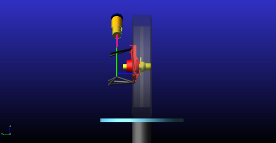
The first attempt consisted simply in rotate the push-rod around the longitudinal axis in order to reduce the distance between the two joints, without modify the rest of the force response subsystem formed by the rocker, the spring-damper element and their mounts. However, this relative rotation between the push-rod and the rocker would imply the first to work mainly incident to the latter. This would introduce the risk of the rocker to bend, since it was mechanically optimized to be loaded in its plane. This must be avoided because it would lead to unexpected increase in resistance to motion of the suspension system.
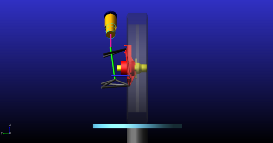
As a consequence, the second attempt has been made with also the rocker rotated around the longitudinal axis and aligned to the push-rod in the static design position, causing most of the forces coming from the push-rod to be transmitted in the rocker plane. It is evident that this configuration can be considered a very satisfying trade-off since it allows a large reduction of the forces, with quite small loads perpendicular to the rocker and with a not very complicated geometry since it needs only a rotation of the rocker mount in a single direction, which is feasible from both design and machining points of view. There is only one problem related to the relative orientation of the rocker with the spring-damper. As a matter of fact, the rotation of the rocker around the global longitudinal axis didn’t allow to maintain the alignment between the two and made the damper to have a certain angle of incidence on the rocker plane, even if very little, producing consequent forces perpendicular to the plane. In addition, this misalignment would bring also inducted rotation of the spring-damper element around its own axis, which would produce additional resistance to suspension motion.
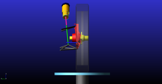
Then, the final configuration can be found considering to solve this last issue, so by rotating both the push-rod and the rocker around the spring-damper element axis. This solution would keep all the elements aligned into a single plane similarly to the initial condition but with a strong reduction of the transmitted force magnitude. However, the rotation around the unusual axis of the damper introduced evident geometrical complications. In the design phase this rotation requires the computation of the rotation matrix around a general axis to be applied on the hard-points of the component to be rotated. While on the design and machining of the mounts it requires solid surfaces rotated in more directions implying a much more difficulty in the process.
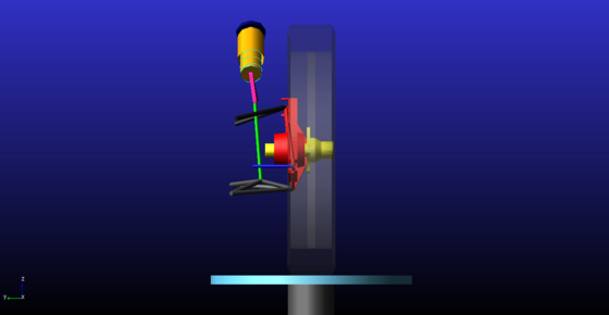
At this point, a comparison of the different configurations in their ability to reduce the transmitted force has been possible, taking as reference result the magnitude of the load on the rocker mount, probably the most stressed point in the system. As a matter of fact, the software allows to track during any simulation the force trend over the suspension motion for any joint, by building a specific Request object.
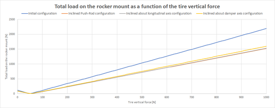
It is possible to notice how all the three possible solutions achieve the objective in reducing the transmitted force to almost two thirds. In addition, it is possible to conclude that the latter configurations is probably the best trade-off that reaches a satisfying reduction in load also avoiding any possible generation of additional motion resistance.
Emanuele Ferrari, Massimiliana Carello and the Team H2politO