Development of a 3 DoF under actuated leg using multidiscipline simulation
This case study deals with the development of a 3 DoF under actuated leg having one flexible component. The whole design and validation was performed using the software MSC.Nastran® and MSC.Adams®-Matlab/Simulink® integrated environment.
Introduction
The aim of the project was to develop a lighter and compliant robotic structure through an integrated approach between mechanics and control. This permits to deeply consider the relationship between structural capabilities and control algorithm requests, but also to exploit the optimal solutions in terms of energy consumption. The whole design based on the hierarchical approach, had the aim of preventing misleading results especially at the initial stage of the design when few data, such as masses, inertias, dimensions were available.
Mechanism description
FLEGX is a 3 DoF under actuated mechanism with one flexible component designed through an extended campaign of numerical simulations. These allowed to investigate the advantages and drawbacks of the different mechanical concepts and to select the configuration that satisfactorily met the jump height performance requirements. Four different FLEGX mechanical solutions, shown in the following table, were designed before reaching the optimal one.
TABELLA
| solution | Characteristics | Pros | CONS |
|---|---|---|---|
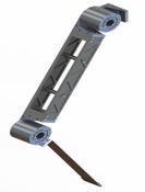 |
Two parallel steel plates for the Upperleg linked together by means of two horizontal steel rods. Actuation system directly coupled with the interested joint. |
Simple and reliable mechanical system. | Low dynamic performances. |
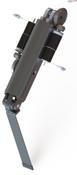 |
Commercial aluminum tube for the Upperleg. Actuation system placed closer to the hip joint |
High torsional stiffness of the Upperleg. | High mechanical complexity and low efficiency. |
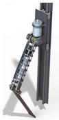 |
Aircraft semi-monocoque fuselage-like structure for the Upperleg. Hip actuators on a linear supporting guide, knee actuator in the Upperleg structure. |
High torsional stiffness of the Upperleg. | High costs and long building time. |
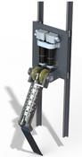 |
Commercial round thin wall aluminum tube for the Upperleg. Whole actuation system placed on a linear supporting guide. |
Good torsional/axial stiffness and low mass. Reduced inertia. Composed by several commercial parts.
|
Numerical simulations
The numerical analyses of the robotic leg were focused on the estimation of deformations and stresses of the flexible link arose during take-off and landing phases of a jump movement. The simulations were performed by requiring that the maximum flexible link stresses, estimated with the Von Mises criterion, were lower than the ultimate tensile strength of the link material (530MPa for a steel component).
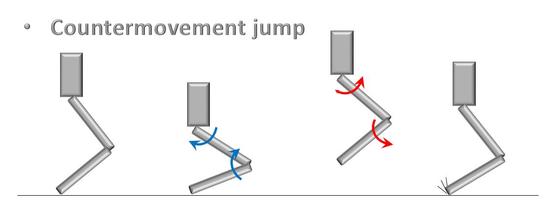
The simulated jumping movement was a countermovement jump: it consists in the following steps:
- The robotic leg starts at a static standing position and then squats down, in 3 seconds, by a 55 degrees clockwise and counterclockwise rotation, with respect to the vertical axis, of the hip and knee joints respectively.
- At t = 3s the hip and knee joints rapidly rotate again, but in the opposite directions, allowing the leg to jump vertically up off the ground.
These rotations were implemented as imposed motions through a combination of several STEP functions.
The flexible component was integrated in the MSC.Adams® environment by means of a modal neutral file (mnf) generated with MSC.Nastran®. This file contains information such as inertia matrix invariants, mode-shapes and frequencies of the modal base derived from fixed boundary eigenmodes through an orthonormalization procedure. In addition, with the aim of reducing the solution time and avoiding solver issues during the simulations, the contact between the flexible link and the ground was modelled by interposing a negligible mass rigid cylinder, constrained by a fixed joint to the lower interface node of the flexible link and the ground. That choice permitted to model the contact between two rigid bodies by using the Impact-Function-Based function that implements a nonlinear spring damper element.
The simulations were run using the GSTIFF implicit predictor – corrector integrator and, with the aim of increasing the stability and robustness of the solver, the SI2 (Stabilized Index 2) formulation was used, avoiding the very short-duration numerical spikes for velocities and accelerations.
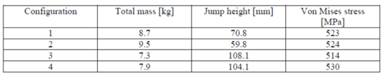
After several preliminary simulations the permissible solution convergence error was set to 1e-4. Jump heights, maximum stresses developed in the flexible link and total mass, defined in the multibody software, for the four mechanical concepts are listed here below:
Results and Conclusions
The solutions No.3 and No.4 shown the best performances with a jump height of 108.1 and 104.1mm respectively. The selected configuration was the number 4 due to the advantages shown in Tab.1.
Autori: