Università: Politecnico di Torino
In control applications, spacecraft are often modelled as a rigid body, which is acceptable if the satellite has no large moving parts and its structure is mainly composed of a single body. However, satellites often have moving parts such as large flexible solar panels, robotic arms, telescopic booms, tethers or liquid fuel. In this case, the dynamic coupling effects between the moving parts are not negligible, and in order to take into account their effects on the overall system dynamics, the rigid-body model must be dismissed. Indeed, in a multi-body satellite the movement of one of the bodies disturbs the position and attitude of the whole space robot. This is due to internal forces and torques exchanged between the bodies at their connection points, i.e. the joints. In addition, the coupling between the flexibility of the structure and the attitude dynamics causes vibrations of the flexible bodies and internal torques acting on the satellite and disturbing the attitude dynamics.
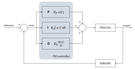
The scope of the thesis is the development of two models to simulate the attitude dynamics of a flexible spacecraft. The first one is based on a mathematical model already present in literature, the second one is implemented through the software Adams. Accurate models of satellite attitude dynamics are of fundamental importance for Guidance, Navigation and Control (GNC) systems. In this work, the navigation system is not studied, and the actual state informations are given by the plant of the system, defined by the attitude kinematics and dynamics. Moreover, the actuator system is represented by the reaction wheels, and the control function is based on a PD controller. Since the primary goal was to validate the flexible spacecraft mathematical model, the same attitude controller has been implemented on both the two models. To make it simpler a basic PD regulator has been chosen, conscious that is not the most efficient controller to obtain high attitude performance.
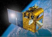 As spacecraft central hub, the main body of the Picard has been selected. Picard is a CNES solar-terrestrial microsatellite, aimed at monitoring the solar diameter, the differential rotation, the solar constant, and to study the long-term nature of their interrelations. Since the main goal of this satellite is to observe the sun, so having a correct continuous pointing towards it, the Picard has been chosen for the attitude control manoeuvre. It is worth to say that the Picard has only one solar panel, while the spacecraft implemented in this case has four solar panels in order to have a symmetric and more general type of spacecraft. The other big difference is about actuators. The Picard has four reaction wheels in pyramidal configuration, while the spacecraft analysed has three reaction wheels located at the Center of Mass (CoM) of the spacecraft, each of them acting on one axis of the body reference system placed at the CoM.
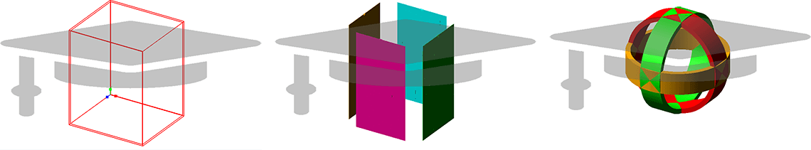
The attitude kinematics of the spacecraft is described through Euler parameters, known as quaternions, from which the Euler angles have been extracted for a better understanding of the manoeuvre. On the other hand, the conservation of the angular momentum is used to compute the equations for the attitude dynamics of a rigid body, known as Euler’s equation. External torques representing external disturbances, like for example the gravity gradient, have been added. Besides that, the internal torques provided by the cluster of three reaction wheels (RWs) are taken into account. The RWs system is modelled with a first order filter and a saturation block for each wheel in Simulink environment. After that, the flexibility of the solar panels has been studied. Three mode shapes (the first and second bending modes and the first torsional mode) are considered and described by the modal coordinate vector, which is coupled to attitude dynamics through a coupling matrix rigid-flexible. This matrix is calculated through a matrix of eigenvectors obtained from a FEM analysis in Patran and MSC Nastran, and it is used to find the disturbing torque and angular momentum of the flexible solar panels. Also a stiffness matrix and a damping matrix play their role and are described by the natural frequencies and the damping ratios of the modes taken into account. In this work the damping matrix is obtained from the stiffness matrix multiplied by a coefficient.

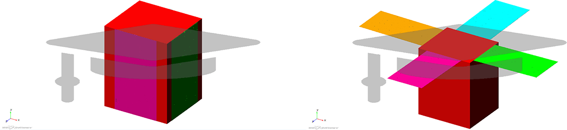
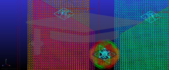
Regarding the implementation of the spacecraft in Adams, the system is composed of three main parts: one central rigid main body or hub, four flexible solar panels (they have become flexible through the Adams sub-tool Adams Flex) and three reaction wheels at the CoM of the system, acting along the three body axes. Each solar panel is linked to the main body structure through a revolute joint; the same is done for the three RWs, which provide the correct control torques acting on the CoM of the system.
The deployment of the panels is simulated through an appropriate design of the hinge motor, modelling the joints as torsional spring-damper with a certain torsional stiffness and preload calculated by a kinematic motion law, aiming at evaluating the hinge torque as function of the deployment angle. Finally, a focus on the braking and stopping phase of the panels has been posed. In particular the BISTOP function has been implemented.
The first mission scenario consists of a manoeuvre of attitude changing aiming at simulating a command for a new pointing direction for the satellite. The spacecraft starts the manoeuvre having already deployed its solar panels for mathematical model, deploying its solar panels for the Adams model. Initially the attitude is represented by the null quaternion q0=[1,0,0,0]T and the goal of the manoeuvre is to reach the Euler angular position [15,5,10]T deg. Finally, at 500 s the spacecraft begins to restore its initial orientation, so [0,0,0]T deg. The simulation stops at 1000 s. The spacecraft has been analysed also in a second scenario where a failure of the deployment of three solar panels occurs.
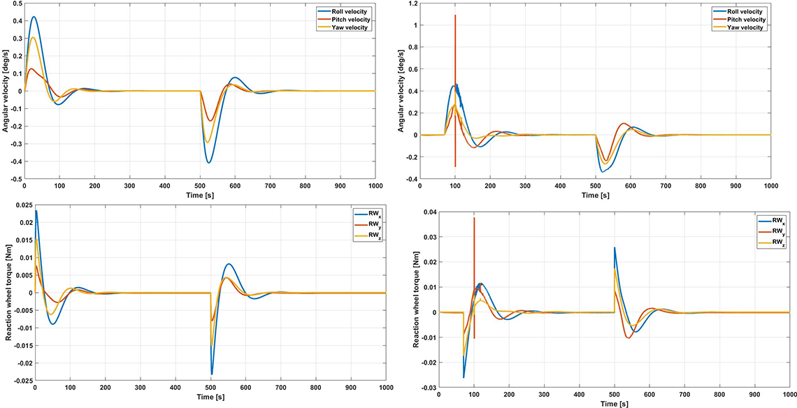
As visible from the results, the PD controller ensures good performance, providing a pretty stable response in both cases, despite some overshoots and little steady state errors.
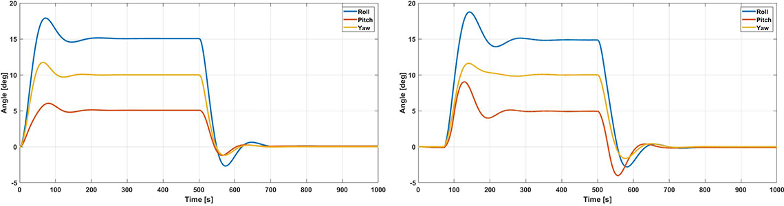
The main difference is at 100.4 s, when a considerable vibration of the panels is read by Adams, while the mathematical model does not. This fact can be explained through the potential of this software to take into account non-linearities and multi-body couplings
In case of failure, the PD controller has a little lack of effectiveness, ensuring a good response along the yaw axis, the most influenced by the deployment on only one panel, but leaving the spacecraft to deviate of very few but not negligible degrees the initial pointing position along the roll and pitch axes.

Anyway, despite the better accuracy of Adams, the mathematical model is a good linear approximation for studying the behaviour of a real spacecraft during a manoeuvre.
Possible future works are relative to the development of a more accurate model in Adams, going to create even more realistic solar panels. Moreover, the position dynamics and control can be implemented, together with the attitude dynamics, to have a complete model of the spacecraft. Besides that, the cluster of reaction wheels can be improved including one more wheel as redundancy. Finally, a more effective controller can be used, in order to reduce overshoots and steady state errors, and trying to counteract non-linearities.
Autore: Gianluca Tagliani
Relatori: Prof. Elisa Capello, Dr. Mauro Mancini, Ing. Daniele Catelani
Anno accademico: 2021/2022