Development of a numerical model for the simulation of the Self Piercing Rivet mechanical joining process and its validation by comparison with experimental data
Politecnico di Milano
– In collaboration with Centro Ricerche Fiat S.C.p.A.
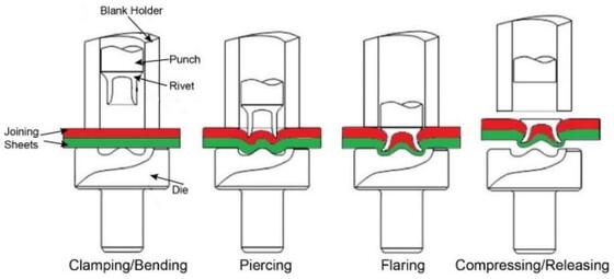
SPR is a method of joining two pieces of material using a rivet without the need for a pre-drilled hole. The basic Self Piercing Rivet process involves driving a rivet at high force through the material layers to be joined into a die which causes the rivet leg to flare out and form a mechanical joint.

Figure 1 - Time sequence of the SPR process
The objective of my investigations has been the realisation of stable and repeatable SPR joints made of flat steel and aluminium sheets, using different dies. For what concerns the 2-thicknesses joint, the validation of the joint went through a FEM simulation of the joining process, followed by experimental tests. Positive results had the double valence of demonstrating not only the reliability of the virtual simulations but also the compliance of the joint with the FCA technical specifications, since it must be realised in a mass production environment, characterised by a certain amount of product variability and a natural deterioration of the process.
The mesh type and sizes represent an important aspect of the FEM as they affect both the CPU time and accuracy of the results. In simulations in which a mesh of the same size was applied to the top and bottom sheets, interpenetration of the elements in the rivet leg occurred.

Figure 2 - Joint cross-section affected by interpenetration
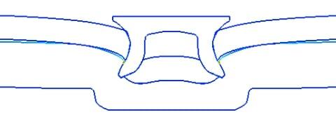
In Simufact.forming using a Marc non-linear solver associated with the use of direct contact methods, penetration between the bodies can be avoided by setting the edge length of the rivet mesh marginally finer compared to that of the top sheet. Similarly, between the top and bottom sheet. This procedure is typical among finite element programs. The direct contact method is based on the definition of touching-touched bodies which allows checking only for nodes of the touching body and reduces the number of times that boundary nodes are used in the creation of contact equations. In this case, the contact directions were assigned in order to treat the rivet as the touching body with respect to the top and bottom sheets, while the top sheet was treated as the touching body with respect to the bottom sheet. Generally finer mesh was used for the touching body and coarser mesh for the touched body.

Figure 3 - Joint cross-section without interpenetration
Evaluating the influence of different friction coefficients assigned in different tests, based on the values proposed by the researchers, a good agreement between the simulation results and the experimental data was found because all the quality criteria imposed by FCA, as well as no cracks or defects in the formed mechanical joint, were observed. This proved the validity of the selected friction coefficients. By comparing the values of the rivet head height, they are very similar to each other, but this is not valid for interlock values and this can be noticed by looking at how far the tip of the rivet leg protrudes beyond the white line, representing the interlock distance in experimental test. This means more expansion of the rivet legs to ensure optimal joint for higher interlock values.

Figure 4 - Influence of friction coefficients on the SPR quality parameters
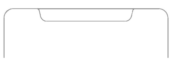
With the latest simulations conducted, I have shown what differences arise from the use of the die with an optimised profile, characterised by a higher depth and greater diameter of the inner cavity:

Figura 5 - Usual die profile

Figura 6 - Optimised die profile
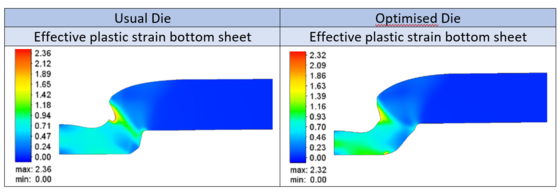
In order to understand the advantages of using a die with an optimised profile, it is necessary not only to consider the quality parameters of the SPR but also the distribution of deformations on the lower sheet. It can be seen the different distributions and how the values obtained with the optimised die configuration are much better, with a reduction in the maximum value, which, as can be seen from the scale of values, goes from 2.36 to 2.32:

Figure 7 - Comparison between effective plastic strains on the bottom sheet
The bottom sheet elongation should be reduced as much as possible to avoid the cracks developing, and this aspect is guaranteed by increasing the lower fillet radius of the mould cavity, in addition an increase in volume of the inner cavity allows the material to flow better inside:

Table 1 - Comparison between main parameters of the two dies
Author: Andrea Corona
Supervisor: Laura Maria Vergani
Co-supervisor: Chiara Colombo
CRF tutor: Stefano Capobianco