Replacement of the stator in a hydroelectric plant turbine
Replacing the stator in a Francis-style hydroelectric turbine using a new procedure with laser measuring equipment.
Contact us
The Francis Style hydroelectric turbines, in simple terms, are driven by water falling from a great height which turns the blades of an impeller at great speed, transforming potential energy into kinetic energy. The impeller is joined to a spindle by means of an axle. The spindle turns inside a stator transforming the kinetic energy of the impeller into electricity.
To function correctly and take advantage of the driving force of the water, the axle of the turbine must be correctly centred so as not to cause wear to the support elements. It is also important that the stator-spindle set remains perfectly centred, as the separation between them, called the air gap, is controlled by opposite forces, one repelling (magnetic force) and the other attracting (centripetal force). If the air gap is uniform, the two forces counteract each other; otherwise, it may cause vibrations which will affect performance.
Any reduction in repair times would provide an important economic benefit, as the plant must maintain the ecological flow of the river. Therefore, during the days when the plant is not operational, the water must still be released, although it does not pass through the turbine and, therefore, does not generate electricity.
 The information obtained from this bearing is its levelling and the position in the space of its centre. In this way, the stator centreline position is obtained(vertical axis that passes through the centre of the bearing). Once the centreline in space is located, it is possible to create various reference points around the turbine, which may be used to recover this position of the centreline each time that they are measured.
Various joined references are also set on the spider. Given that once the new stator is put into position the spider must be in the same position as it was with the old stator, these reference points assist us in ensuring that this is achieved.
There was another additional problem: due to the age of the equipment, there were no plans indicating the position of the holes and joints to attach the stator to the spider and to the floor foundation. To carry out the machining of these elements in the new housing, the new stator had to be placed in its position within the set, marking the position of the holes and joints.
Then, the new stator had to be disassembled again to make the holes and countersinks and to perform the necessary reaming, before the assembly of the final stator and spider. This problem is easily resolved by measuring the position of all the holes and joints of the stator before it is removed, using (AT901LR) laser equipment. Thus, the position of the centre and the diameter of each of the holes and joints is determined such that, when the new stator arrives to the hydroelectric plant, it already has all of machining necessary for its installation.
All of this information relating to the holes of the stator is sent referenced to the position of the wiring outlet. In this way, we ensure that not only the holes on the stator coincide with those corresponding with the spider and the floor, but also that we respect the outlet position. This makes it unnecessary to change or modify any element of the electrical wiring inlet or outlet. Once the old stator is removed, the spindle is measured to determine the height of its magnetic pack and also its centre. If we make sure that the centre of the new stator coincides with the centre of the spindle, we will improve the performance of the turbine. When the new stator arrived at the hydroelectric plant, an initial measurement was performed. During this process, performed with (AT901LR) laser equipment, its circularity was checked and its centreline determined. Various reference points were set on its outside housing, which enable us to recover the position of its centreline each time it is measured.
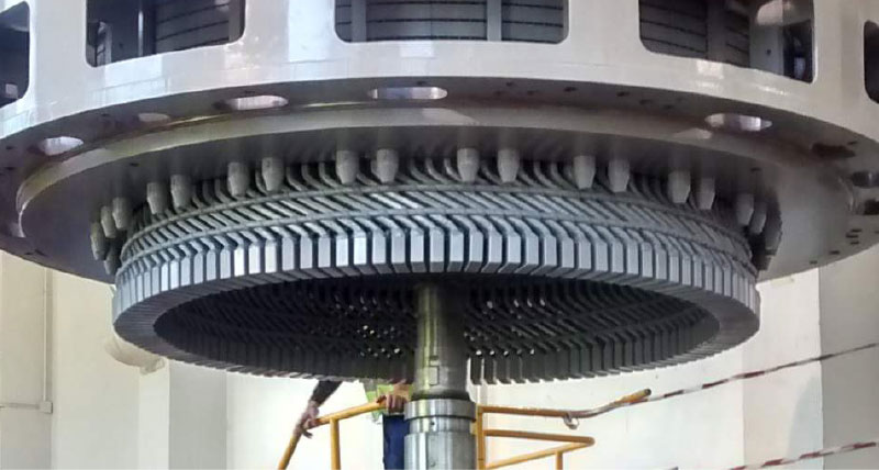
Placement of the stator was carried out with the spindle already in position. Due to the small radial separation (16 mm air gap), there existed a serious risk of the pieces crashing together during handling. By measuring the references on the new stator housing and those located around the turbine, it was possible to know, at all times, the position in the space of the stator with reference to what its final position would be.
Thus, it was possible to provide the bridge crane operators with the corresponding corrective actions. In addition, performing the work in this way, technical personnel were not placed at risk, since the measurements were performed at a distance using (AT901) laser equipment, so it was not necessary for anyone to come into contact with moving elements. Therefore, the work could be carried out more safely. As the stator arrives to its final position, gauges are used to level it correctly and position it vertically, thus ensuring that the heights of the stator and rotor magnetic pack centres are aligned. Finally, using adjustment screws, the centreline of the stator is centred and placed in the correct angular position, corresponding to the same position as the old stator.
At this point, the position of the joint holes are checked to ensure that they align with the position of those on the floor. Once the stator is fixed in its final position, the spider is put back in place. As stated previously, a series of reference points had been set which, when measured again, also allow us to make movement corrections until the original position is obtained. Thus, we ensure that the axle support bearing (that is part of the spider) also remains in the same position that it previously had. At this point, the position of the joint holes for connecting the spider is checked to ensure that they are aligned.
To function correctly and take advantage of the driving force of the water, the axle of the turbine must be correctly centred so as not to cause wear to the support elements. It is also important that the stator-spindle set remains perfectly centred, as the separation between them, called the air gap, is controlled by opposite forces, one repelling (magnetic force) and the other attracting (centripetal force). If the air gap is uniform, the two forces counteract each other; otherwise, it may cause vibrations which will affect performance.
Procedure
Standard procedure
The standard method for replacing the stator requires the complete disassembly of the turbine. Later, to centre and realign, we need to use as a reference the vertical plumb line (for the alignment) and the position of the labyrinth (to centre). The disassembling, centring and assembling processes of the turbine pieces take various weeks and require qualified staff.Any reduction in repair times would provide an important economic benefit, as the plant must maintain the ecological flow of the river. Therefore, during the days when the plant is not operational, the water must still be released, although it does not pass through the turbine and, therefore, does not generate electricity.
New procedure
New The aim of the new procedure is to determine the position of the original stator prior to its removal, so that afterwards the new stator can be placed in that position, without changing the centre of the turbine.Methodology
As indicated, the position of the original stator needed to be determined prior to its removal. To do this, we measure the upper spider (the upper bearing support bracket which also supports the entire weight of the set), which is joined to the stator and upon which the centreline bearing is assembled.The information obtained from this bearing is its levelling and the position in the space of its centre. In this way, the stator centreline position is obtained(vertical axis that passes through the centre of the bearing). Once the centreline in space is located, it is possible to create various reference points around the turbine, which may be used to recover this position of the centreline each time that they are measured.Various joined references are also set on the spider. Given that once the new stator is put into position the spider must be in the same position as it was with the old stator, these reference points assist us in ensuring that this is achieved.
There was another additional problem: due to the age of the equipment, there were no plans indicating the position of the holes and joints to attach the stator to the spider and to the floor foundation. To carry out the machining of these elements in the new housing, the new stator had to be placed in its position within the set, marking the position of the holes and joints.
Then, the new stator had to be disassembled again to make the holes and countersinks and to perform the necessary reaming, before the assembly of the final stator and spider. This problem is easily resolved by measuring the position of all the holes and joints of the stator before it is removed, using (AT901LR) laser equipment. Thus, the position of the centre and the diameter of each of the holes and joints is determined such that, when the new stator arrives to the hydroelectric plant, it already has all of machining necessary for its installation.
All of this information relating to the holes of the stator is sent referenced to the position of the wiring outlet. In this way, we ensure that not only the holes on the stator coincide with those corresponding with the spider and the floor, but also that we respect the outlet position. This makes it unnecessary to change or modify any element of the electrical wiring inlet or outlet. Once the old stator is removed, the spindle is measured to determine the height of its magnetic pack and also its centre. If we make sure that the centre of the new stator coincides with the centre of the spindle, we will improve the performance of the turbine. When the new stator arrived at the hydroelectric plant, an initial measurement was performed. During this process, performed with (AT901LR) laser equipment, its circularity was checked and its centreline determined. Various reference points were set on its outside housing, which enable us to recover the position of its centreline each time it is measured.
Placement of the stator was carried out with the spindle already in position. Due to the small radial separation (16 mm air gap), there existed a serious risk of the pieces crashing together during handling. By measuring the references on the new stator housing and those located around the turbine, it was possible to know, at all times, the position in the space of the stator with reference to what its final position would be.
Thus, it was possible to provide the bridge crane operators with the corresponding corrective actions. In addition, performing the work in this way, technical personnel were not placed at risk, since the measurements were performed at a distance using (AT901) laser equipment, so it was not necessary for anyone to come into contact with moving elements. Therefore, the work could be carried out more safely. As the stator arrives to its final position, gauges are used to level it correctly and position it vertically, thus ensuring that the heights of the stator and rotor magnetic pack centres are aligned. Finally, using adjustment screws, the centreline of the stator is centred and placed in the correct angular position, corresponding to the same position as the old stator.
At this point, the position of the joint holes are checked to ensure that they align with the position of those on the floor. Once the stator is fixed in its final position, the spider is put back in place. As stated previously, a series of reference points had been set which, when measured again, also allow us to make movement corrections until the original position is obtained. Thus, we ensure that the axle support bearing (that is part of the spider) also remains in the same position that it previously had. At this point, the position of the joint holes for connecting the spider is checked to ensure that they are aligned.