The first complete industrial assembly process based on laser measurements
Challenges of very-large-scale assembly
Contact us
The Airbus A380 is the most modern, spacious and capable civilian aircraft of all time. It was first shown in December 2000, christened “The Flagship of the 21st Century.” The plane was developed in close cooperation with air carriers, airports and air traffic authorities.
The aircraft incorporates the most modern technologies in terms of materials, systems and industrial processes, adhering to the strictest international standards for registration approval. Airbus’ European sites in France, Germany, the United Kingdom and Spain participate in the design and assembly of the A380 aircraft.
The Jean-Luc Lagardère site in Toulouse was specially constructed for the A380: final assembly takes place there. The assembly line for the youngest Airbus consists of several segments. The first unit deals with the assembly of the weight/bearing parts of the aircraft. The second unit conducts tests on the assembled aircraft and installs the powertrains. The third unit conducts the open-air tests that prepare the aircraft for its first flight.
New challenge for the assembly
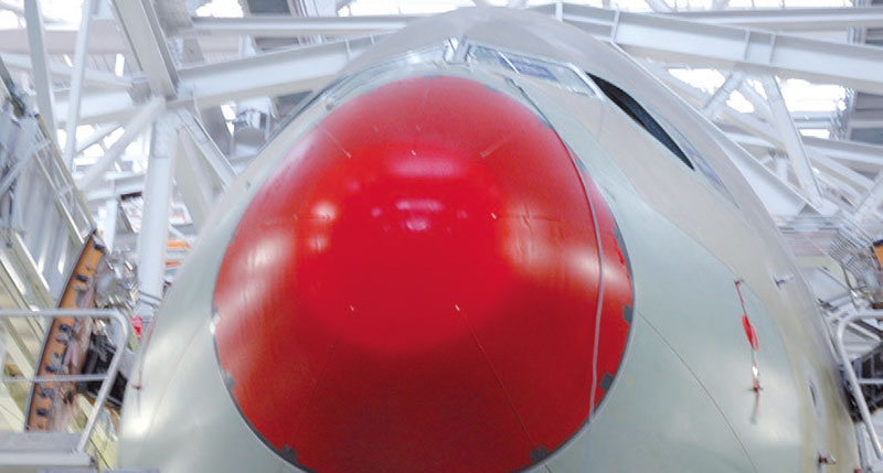
Station 40 of the first unit is in charge of the final assembly of the aircraft (both segments and wings). For this purpose, different parts are compared to one another. Strict part geometries have to be adhered to. The project for the assembly of the A380 was begun in 1998. Numerous new challenges had to be mastered: the extraordinary size of individual segments, the oval shape of the aircraft itself (round on other aircraft), double-decker fuselage, and so on. Besides, the tools used for the A340 had to be carried over. These tools had to be adjusted with very high accuracy to allow for the final assembly of the aircraft, and they have to be inspected regularly because they guarantee the correct positioning of different plane segments in space. The basic concept behind the new assembly method was to inspect the aircraft directly, that is, to inspect its individual segments in relation to one another rather than to use the tools as a reference system, avoiding the whole issue of compounding tolerances. The second task was to find a solution for assembling complex interfaces (i.e. the oval shape of the fuselage and the double-decker aircraft layout). The concept of assembly based on laser-based measurements was selected by the executives in charge of the A380 program.
Thanks to the capable and dependable Laser Trackers from Leica Geosystems, aircraft assembly based on laser measurements is a technologically mature process and can be carried over to other programs within our organization.
Thierry Fabre, in charge of laser-based measurements at the Toulouse site, explains: “The challenge of this task had gone well beyond typical assembly. We needed to come up with a common aircraft reference system for all European Airbus sites. Different sites had different working methodologies, their own goals and their own constraints. The preparatory stage was crucial in making sure that the data from various sites are mutually intelligible.”
Selection of Leica Geosystems: logical step
Numerous projects with the involvement of Leica Geosystems Laser Trackers had taken place in the past on various Airbus sites in France (RCT in Nantes, Erebus in Meaulte, assembly station 15/21 in St. Nazaire, segment interface measurements on the A320 project in Toulouse), as well as in Bremen, Germany and Broughton and Filton in the United Kingdom.
 Martial Charraud, who had previously worked on the sites in Nantes (RCT) and Toulouse (A320), is part of the Thierry Fabre A380 team. He explains: “The first projects on Airbus fuselage assembly by means of laser measurements were developed in close cooperation with the Leica Geosystems headquarters in Switzerland. Having had very positive feedback based on past measurement jobs, we of course approached Leica Geosystems when we were looking for a solution for the work to be done on the A380. The goal was to use our experience with the company and apply it to this new project. Besides, I am very familiar with the Leica Geosystems products and know how reliable they are.” The A380 assembly line will be used for about 30 to 40 years. This makes selecting good, long-term, dependable partners all the more important. The systems used, especially computer software and automation software, are made obsolete very fast. “Serviceability of old systems is extremely important. We have agreed to long-term cooperation with Leica Geosystems. We have a guarantee that if our instruments are subjected to extreme environmental conditions, they will still function as specified,“ Fabre emphasizes.
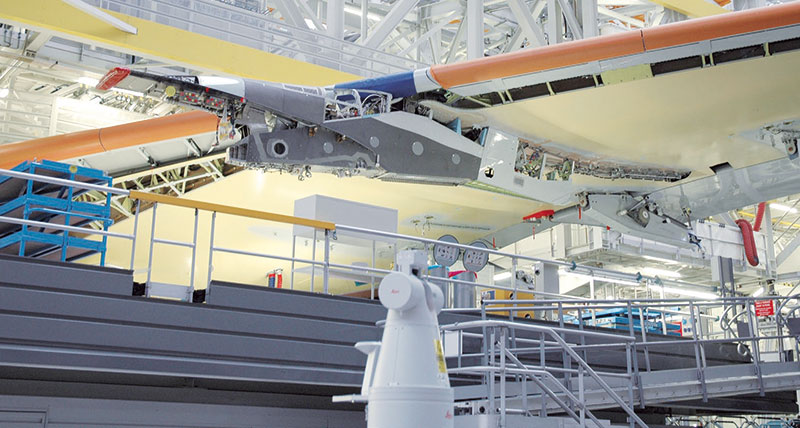
Pre-assignment of line of sight
After installing the tools and settling on the adjustment methods, the laser tracker line of sight in very tight quarters had to be analyzed with CAD software. Due to a large number of platforms and structures making up the assembly line, it is very difficult to guarantee the availability of line of sight between measurement points and the laser tracker. “We had to come up with a concept that determines the number of laser trackers needed and the optimal position of each individual laser tracker. This was a particularly challenging task,” continues Charraud.
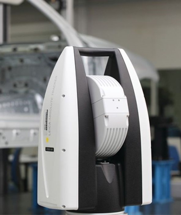
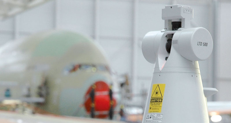
Four laser trackers from Leica Geosystems were selected
At first, four Leica Laser Trackers were chosen: two for the fuselage and two for the wings. All four laser trackers are intertwined and connected by a common coordinate system. This arrangement guarantees the uniformness and mutual interchangeability of the laser trackers.
The specially developed control and measurement software interfaces with the Leica Geosystems EmScon software. Leica Geosystems helped during the script development stage. “The support we received from Leica Geosystems was essential in assuring the compatibility of the software and in guaranteeing that the correct functions are being utilized,” adds Charraud.
A simplified human-machine interface
 Because the measurement system is integrated into the fuselage assembly process, controlled by the assembly workers, they were involved in the development of the human-machine interface from the very beginning. The overall goal was to make using the measurement instruments as simple as possible, especially because most users are not metrology specialists. To make assembly tools as simple as possible, complicated processes had to be taken care of beforehand: automatic control and target location, on-screen result display for determining the correct part positioning, and so on.
Final measurement equipment inspection and adjustment even before the first plane was built
An added difficulty of the project was the fact that the entire measurement system had to be inspected even before the first aircraft was present on the assembly line – neither fuselages nor wings war available at that time. Therefore, test and inspection procedures had to be developed that effectively simulated the dimensions of the aircraft. The first-ever aircraft (MSN O1) has allowed the team to inspect the entire measurement system in a 1:1 scale.
Success is in the air
“Permanent improvements and the increases in the output mandate even better dependability and improvements to the aircraft-segment positioning procedure in order to reduce cycle times – this is one of our main concerns both today and in the future. These improvements include optimizing the algorithms for the positioning of aircraft parts to one another,” explains Fabre and continues, “Thanks to the capable and dependable Laser Trackers from Leica Geosystems, aircraft assembly based on laser measurements is a technologically mature process and can be carried over to other programs within our organization. After the measurement methods we developed were carried over to the military A400M project, the will most likely be used on the upcoming A350 program as well!”