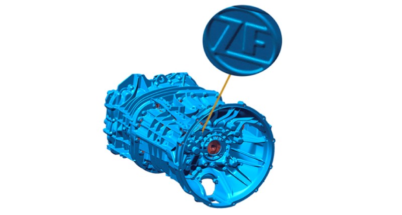
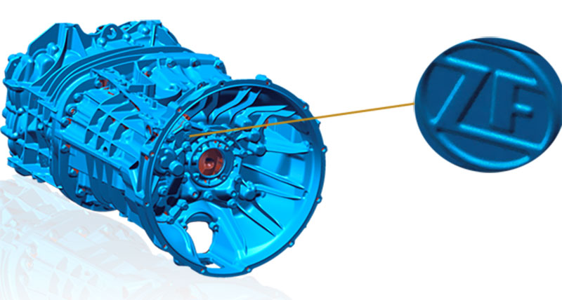
3D quality inspection of gear transmission casings for commercial vehicles
ZF Friedrichshafen - Germany.
Contact us
Based on the casing created in the CAD system, die‑casting molds are produced to serve as shaping molds for the casing components. In the actual production process different parameters such as the filling quantity, pressure, temperature conditions, timing and tool design determine the condition of the molding parts. In order to ensure consistent quality of the die-casting parts, the adherence to the predefined tolerances has to be continuously verified.
This is when the high resolution 3D measurement and inspection system SmartScan comes into play. The optical metrology technique developed and applied by Hexagon offers the ideal solution for quality assurance in the areas of first sample inspection or serial production. The application range stretches from laboratory measurements all the way to automated process solutions, thereby ensuring the acquisition of high-precision data even when executed in the factory environment.
Diverse tasks for 3D scanners
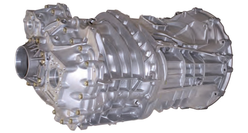
The inspection tasks at ZF for gear transmission casings made of aluminum die-cast are versatile: Firstly, in order to make sure of the required quality in the prototype phase precise three-dimensional data is needed for the first sample inspection. The purpose and objective of the construction is the highest level of rigidity of the casing while using a balanced material input.During the serial production, precision is of key importance when it comes to maintaining the quality standard. This is when the casing is inspected for contour accuracy and the surface is examined for damages and deformations. A special inspection parameter in this context is the wall thickness, which has to be of optimum proportion with regard to stability and quantity of material used.
Finally, the tools used in the production process have to be regularly inspected in order to make sure that signs of wear and tear are being identified at an early stage, thus avoiding the development of inferior product quality well ahead of time.
All inspection processes can either be carried out manually on a turn table or automated in combination with a robot (serial inspection).
Detailed capture of complex components
For the first sample inspection, the SmartScan with a 250 watt light and a big measuring field is being used. To execute the partially automated data acquisition of the transmission casing, the sensor setup is additionally equipped with the rotation unit TurnTable-300, which is specifically designed for heavy weight measuring objects.During the scanning process, firstly the individual scans are generated, aligned and then merged into a uniform polygon mesh with the aid of the OptoCat software. In a second step, the generated data is imported into the inspection software (in this case PolyWorks® | Inspector™ by InnovMetric Software Inc.) in order to assess the geometries of the measuring object.
The workflow in detail: Using the standard triangulation angles of area-based scanning systems, deep ridge structures very often cannot be captured with the desired accuracy. Thanks to the flexible sensor configuration of the SmartScan series, scan processes can be carried out using triangulation angles of 30°, 20° and 10°, thus allowing the generation of highly precise measuring data even of object areas which are usually very difficult to capture using conventional sensors.
1. Measuring setup and digitisation
- Setup of sensor, turn table and measuring object
- Sensor calibration and verification (VDI 2634/2) according to a dumbbell artifact
- Measurement of the transmission casing (scanning and visualisation)
- Generating the 3D data set (format: STL or PLY)
2. Comparison with CAD data
- Establishing the inspection parameters as per definition (features, cross-sections, scaling)
- Nominal/actual comparison (color deviation comparison with CAD)
- Generation and evaluation of the inspection report
- Optimisation of the die-casting mold and adaptation of the production parameters
 If the CAD tool data is already available, it is directly loaded as reference. Typically, the measured deviations between target and actual status are visualised with the help of a false color map. This way, the measuring results can be easily and directly interpreted and immediately used for the optimisation of the die mold tool or the process parameters. This helps the production department to maintain a consistent efficiency even under demanding circumstances and in the end result to ensure the production of high quality gear transmission casings.
In comparison to the conventional coordinate measurement technology, the SmartScan allows a much easier and faster evaluation of the measuring result, in particular of freeform surfaces. Furthermore, the user is provided with a much more comprehensive data base for subsequent processing, which in the context of the development of the prototype allows a significant reduction of the time to market cycle.
We give thanks to ZF Friedrichshafen AG for their friendly support in creating this case study.