Whitepaper: Modern CMM design concepts
Historically, improvements in CMM measurement accuracy were almost entirely driven by the mechanical accuracy of the CMM's hardware and the ability to maintain the thermal stability of the operating environment.
Contact us
Coordinate Measuring Machines (CMMs) are used in practically every industry that requires precise dimensional inspection of manufactured parts. In today's competitive environment, manufacturers demand CMMs that are accurate, reliable, fast, economical, and provide maximum flexibility with respect to operating environment.
In order to meet these often conflicting requirements and provide maximum value in the products delivered to their customers, CMM manufacturers must make informed design decisions, intelligent material choices, and employ novel techniques.
In order to meet these often conflicting requirements and provide maximum value in the products delivered to their customers, CMM manufacturers must make informed design decisions, intelligent material choices, and employ novel techniques.
Global CMM
The end result should be an affordable machine that is highly accurate, measures parts quickly, and is relatively insensitive to its environment. The key to achieving this goal is the careful management of the machine's intrinsic error.
Historically, improvements in CMM measurement accuracy were almost entirely driven by the mechanical accuracy of the CMM's hardware and the ability to maintain the thermal stability of the operating environment. Thus, in the earliest days of the industry, in order to achieve the ever increasing measurement accuracy required to support shrinking part tolerances, CMM components needed to be manufactured ever more accurately: machine frames were made stiffer, guide ways straighter, drives smoother, scales more accurate, and so on.
At the same time, the operating environment needed to be controlled more and more tightly to reduce the effects of thermally induced measurement errors. The impact of this design direction was increasing expense to the customer, due to the ever increasing amounts of value added to the physical components. Clearly, this path could not continue indefinitely both from the perspective of expense, and from diminishing returns of tighter and tighter specifications for mechanical and thermal accuracy — it is impossible to build a structure without any error at all; some intrinsic structural error will always remain. What was needed was some sort of paradigm changing advance in order to satisfy the increasing demand for accurate, reliable, fast, and economical CMMs, while also providing flexibility with respect to operating environment.
The introduction and continual refinement of software based measurement error compensation techniques over the past few decades have allowed CMM manufacturers to break this trend and effectively meet their customer's requirements. That said, software based measurement error compensation is not a cure-all for design problems, nor does it allow CMM manufacturers to apply sloppy design principles, make inappropriate material choices, or skimp on build quality.
At its most basic level, a CMM provides a coordinate system which defines the location of data points in space. This coordinate system is physically realized in the mechanical structure of the CMM using linear scales. Some type of probing system is used in conjunction with the linear scales to identify the location of measurement points on the part being measured. In the case of a theoretical CMM with a "mechanically perfect" structure, the X, Y, and Z scale readings would perfectly correspond to the actual position of the probe tip on the part. In reality, since the "mechanically perfect" CMM does not exist, many error sources contribute to a small difference between the scale readings and the true probe position. This is defined as the measurement error.
The concept of how to compensate for the intrinsic error present in any CMM structure was solved with software error compensation, which is based on the idea that if we can understand and mathematically characterize a CMM's predictable measurement error sources, the CMM controller software can automatically correct the measurements. In this context, software error compensation is simply a method for correcting CMM scale readings for systematic errors in the probe tip position as reported by the CMM scales.
This feature was first introduced on CMMs a few decades ago. Over time, these compensation techniques have grown increasingly more sophisticated, encompassing both static geometric errors and all sorts of dynamic and thermally induced geometry errors. Static geometric errors are those errors caused by microscopic imperfections in the shapes of the guide ways and scale systems that lead to errors in the measured location of the probe tip when the machine is not moving. Thermal errors are changes in the machine's geometry caused by changes in temperature. In its most basic form, thermal error correction includes simple linear correction of the scales due to thermal expansion and contraction to more elaborate methods for compensating for thermally induced nonlinear changes in the structure.
Since it is only feasible to correct for known, well characterized systematic errors, an important prerequisite for the successful application of software error compensation is a "well behaved", repeatable CMM. That is, a CMM based on robust design principles and built with quality components by a staff of highly skilled technicians who are trained to assemble a machine with the highest possible mechanical build quality.
The main CMM structural design parameters include the weight of the moving mass and the static, dynamic, and thermal properties of the physical structure. The use of lightweight components in the moving part of the structure reduces the forces necessary to accelerate them during machine motion, resulting in the ability to use less powerful and cooler running motors while at the same time causing less frame distortion due to inertia.
The design challenge is to find a good compromise between stiffness and weight. Thus, material selection is extremely critical, especially since it affects the other requirements of thermal stability and dynamic properties. Aluminum is especially attractive in this respect. Although it has a specific weight that is similar to that of granite, modern extrusion processes allow for the manufacturing of large structural aluminum elements with the material located specifically where it has the greatest impact on stiffness. Relatively thin wall structures with the material farther away from the neutral axis of bending will result in the most structural stiffness with the least amount of weight. It is important that the build up of thermal gradients within the structure are minimized in order to minimize frame distortion.
Gradients can build up when a component slowly responds to temperature changes. A good example is a large slab of granite exposed to a temperature change. Because of the granite's low thermal conductivity and large mass, heat will only slowly move through the material. This results in a non-uniform temperature distribution within the granite. If this distribution is asymmetric (top and bottom with respect to the center), this will result in differences in expansion or contraction of the top and bottom surfaces and consequently bend the granite. (Yes, believe it or not, granite does bend!) On the other hand, aluminum has a high coefficient of thermal conductivity; heat enters an aluminum structure and quickly transfers through the material, avoiding the build up of thermal gradients and the resulting bending.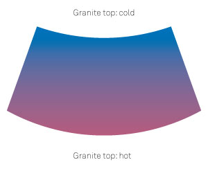
Granite's low coefficient of thermal conductivity results in slow heat conduction which can result in large thermal gradients within a thick slab of granite. As shown in the illustration (exaggerated for clarity), this causes the granite to bend as the opposing surfaces expand or contract differently. Aluminum on the other hand quickly conducts heat due to its much higher coefficient of thermal conductivity, thus avoiding thermally induced geometric distortion.
How do these design concepts play out in a real CMM design? The Brown & Sharpe Global CMM, a moving bridge, air bearing CMM manufactured by Hexagon Manufacturing Intelligence, Inc., is a well known example of the application of modern CMM design principles. For Global, the main design drivers were accuracy, throughput, and environmental flexibility. Granite is used for the fixed base of the CMM that the moving bridge travels on.
Even with its poor thermal properties, granite is still an excellent choice for a high quality flat work surface with extreme durability. Improvements in granite machining processes permit the manufacture of a one-piece granite base with integrated guide ways for the air bearings. In addition, the Global granite base is heavy and, in combination with passive elastomeric isolation pads, this serves to isolate the machine from environmental vibrations which have a negative effect on accuracy and repeatability.
Tricision
From a thermal point of view, the choice of granite is less favorable because the large granite base is prone to thermal bending resulting from temperature changes within the installation environment. However, this thermal bending is very predictable and well suited for software error compensation. Multiple temperature sensors on the top and bottom of the granite base are used to correct for the geometry errors in the CMM structure that result from the thermally induced granite bending, even when this bending is asymmetric. This compensation method has proven very effective in practice.
Aluminum and steel have dissimilar thermal expansion properties which can lead to problems if the design of the interface between the materials is not designed correctly. If two materials with disparate thermal expansion properties are rigidly joined, they tend to distort in difficult to predict ways. The Global design solves this problem by the way the steel scales are applied to the aluminum structure; the scales are fixed to the machine structure at one end and allowed to expand and contract along the scale's entire length independently of the aluminum structure. Thus, the two materials are permitted to expand and contract independent of one another in a well behaved and predictable manner and the error introduced by the well behaved linear expansion of the steel scales is easily corrected.In contrast to the static base, Global's moving bridge structure is made entirely of aluminum extrusions and castings. As we know, aluminum has good thermal properties with respect to CMM design. However, the scales, which ultimately determine the position of the probe within the CMM measurement volume, are made of steel.
Global's X-beam and Z-rail are aluminum extrusions, while the legs and XZ-carriage are aluminum castings. As we discussed earlier, granite is a good solution for the static base, but it is less than ideal for the moving structure. While it makes good design sense to compensate for thermal granite bending in the base — to take advantage of its desirable work surface properties — it's all downside when it comes to the moving structure. Aluminum for the moving bridge components provides stiffness, light weight, and thermal stability which are some of the key elements that make the Global CMM accurate, fast, and relatively insensitive to its thermal environment.
Global CMMs use both static geometric and thermal error compensation techniques in order to achieve high accuracy and environmental flexibility. The method for compensation of static geometric errors consists of four main steps:
The Global error map is based on a general kinematic model of three nominally perpendicular axes. The purpose of this model is to calculate the combined effect of all the geometric errors of all axes on the position of the probe tip. This combined effect is the error correction that is added to the scale readings.
The corrections for granite bending and scale expansion and contraction described above are examples of thermal error compensation used in the Global design. Recall that thermal errors are changes in machine geometry caused by changes in the thermal environment. The effects of thermal errors on the location of the probe tip are identical to the effect of static geometric errors. The main difference is their root cause. Static geometric errors are a property of the completely assembled machine only. In principle they do not change over time. Therefore they can be captured at one point in time and stored in a data file.
In contrast, thermal errors are a function of both the thermal environment and the machine's thermal response. These errors change constantly unless the machine is located in a tightly temperature controlled environment. In order to calculate the effects of the thermal errors on the location of the probe tip we need a temperature model that characterizes the machine thermal behavior as well as input values that characterize the thermal environment. The input values are machine surface temperatures measured by temperature sensors at various locations on the machine.
Although some models use more sensors, most Global models use eleven temperature sensors placed throughout the structure: two sensors per axis to compensate for linear expansion and contraction of the scales, four sensors on the granite (two on the top and two on the bottom) to compensate for granite bending, and one on the part being measured.
In summary, the design of the modern CMM includes tradeoffs involving accuracy, throughput, and environmental flexibility to name a few of the most important parameters. By making intelligent design decisions involving the selection and application of the appropriate materials and taking full advantage of software error compensation, today's CMM designer can balance CMM design parameters to provide real-world metrology solutions.
Eric Bennett is a Product Manager with Hexagon Manufacturing Intelligence, with product marketing responsibilities for the bridge coordinate measuring machines at the company's Quonset Point, Rhode Island headquarters. Eric has more than a decade of experience in the field of coordinate metrology and holds a Bachelor of Arts degree in Physics and Master of Science degrees in both engineering physics and computer science.
Wim Weekers is the Chief Metrologist at Hexagon Manufacturing Intelligence. Wim was born in the Netherlands and holds a PhD in mechanical engineering from the Eindhoven University of Technology, where he specialized in precision engineering and metrology. Wim moved to the United States in 1997 where he has worked for Hexagon Manufacturing Intelligence performing industry leading research and development ever since. His main areas of interest are CMM accuracy, error compensation, and testing. (CMMs) are used in practically every industry that requires precise dimensional inspection of manufactured parts. In today's competitive environment, manufacturers demand CMMs that are accurate, reliable, fast, economical, and provide maximum flexibility with respect to operating environment.
Aluminum and steel have dissimilar thermal expansion properties which can lead to problems if the design of the interface between the materials is not designed correctly. If two materials with disparate thermal expansion properties are rigidly joined, they tend to distort in difficult to predict ways. The Global design solves this problem by the way the steel scales are applied to the aluminum structure; the scales are fixed to the machine structure at one end and allowed to expand and contract along the scale's entire length independently of the aluminum structure. Thus, the two materials are permitted to expand and contract independent of one another in a well behaved and predictable manner and the error introduced by the well behaved linear expansion of the steel scales is easily corrected.In contrast to the static base, Global's moving bridge structure is made entirely of aluminum extrusions and castings. As we know, aluminum has good thermal properties with respect to CMM design. However, the scales, which ultimately determine the position of the probe within the CMM measurement volume, are made of steel.
Global's X-beam and Z-rail are aluminum extrusions, while the legs and XZ-carriage are aluminum castings. As we discussed earlier, granite is a good solution for the static base, but it is less than ideal for the moving structure. While it makes good design sense to compensate for thermal granite bending in the base — to take advantage of its desirable work surface properties — it's all downside when it comes to the moving structure. Aluminum for the moving bridge components provides stiffness, light weight, and thermal stability which are some of the key elements that make the Global CMM accurate, fast, and relatively insensitive to its thermal environment.
Global CMMs use both static geometric and thermal error compensation techniques in order to achieve high accuracy and environmental flexibility. The method for compensation of static geometric errors consists of four main steps:
- Measurement of errors on each individual Global CMM (data collection)
- Calculation of correction values and storage in a correction table (the error map)
- Application of error correction values by the controller software during CMM operation
- Verification of CMM performance
The corrections for granite bending and scale expansion and contraction described above are examples of thermal error compensation used in the Global design. Recall that thermal errors are changes in machine geometry caused by changes in the thermal environment. The effects of thermal errors on the location of the probe tip are identical to the effect of static geometric errors. The main difference is their root cause. Static geometric errors are a property of the completely assembled machine only. In principle they do not change over time. Therefore they can be captured at one point in time and stored in a data file.
In contrast, thermal errors are a function of both the thermal environment and the machine's thermal response. These errors change constantly unless the machine is located in a tightly temperature controlled environment. In order to calculate the effects of the thermal errors on the location of the probe tip we need a temperature model that characterizes the machine thermal behavior as well as input values that characterize the thermal environment. The input values are machine surface temperatures measured by temperature sensors at various locations on the machine.
Although some models use more sensors, most Global models use eleven temperature sensors placed throughout the structure: two sensors per axis to compensate for linear expansion and contraction of the scales, four sensors on the granite (two on the top and two on the bottom) to compensate for granite bending, and one on the part being measured.
In summary, the design of the modern CMM includes tradeoffs involving accuracy, throughput, and environmental flexibility to name a few of the most important parameters. By making intelligent design decisions involving the selection and application of the appropriate materials and taking full advantage of software error compensation, today's CMM designer can balance CMM design parameters to provide real-world metrology solutions.
Eric Bennett is a Product Manager with Hexagon Manufacturing Intelligence, with product marketing responsibilities for the bridge coordinate measuring machines at the company's Quonset Point, Rhode Island headquarters. Eric has more than a decade of experience in the field of coordinate metrology and holds a Bachelor of Arts degree in Physics and Master of Science degrees in both engineering physics and computer science.
Wim Weekers is the Chief Metrologist at Hexagon Manufacturing Intelligence. Wim was born in the Netherlands and holds a PhD in mechanical engineering from the Eindhoven University of Technology, where he specialized in precision engineering and metrology. Wim moved to the United States in 1997 where he has worked for Hexagon Manufacturing Intelligence performing industry leading research and development ever since. His main areas of interest are CMM accuracy, error compensation, and testing. (CMMs) are used in practically every industry that requires precise dimensional inspection of manufactured parts. In today's competitive environment, manufacturers demand CMMs that are accurate, reliable, fast, economical, and provide maximum flexibility with respect to operating environment.