Model-based definition promises big dividends for quality assurance
Inspection planning greatly enhanced with MBD and GD&T
Contact us
In the long evolution of 3D CAD, you would not think innovative progress is possible at this point. Take Model-Based Definition, or MBD, a term and methodology long tossed around by software developers and the aerospace industry. Surprisingly, there is significant activity in this area, and this technology can bring genuine value to the manufacturing table.
MBD “gold” lies in its ability to streamline product development into a drawing-free process based on an information-rich 3D CAD model that fully defines and provides specifications for parts and assemblies. This next-generation approach to product design has several time- and money-saving ramifications from simplifying manufacturing operations to greatly improving inspection processes.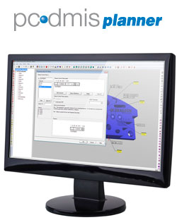
In the quality assurance world, the main problem with the typical CAD model is that it requires a separate blueprint to determine datum structure, key characteristics, and tolerancing to create an inspection plan. This scenario occasionally requires access to the product designer to interpret some of the GD&T information, which is not exactly convenient for multinational corporations. Stir in the nagging question of whether the CAD data or the print is the most current revision, and you have a recipe for convolution.
MBD has arrived on the scene to alleviate this complexity, as several CAD software packages now allow for embedded GD&T. All pertinent product information and inspection planning data is incorporated into one version-controllable entity - the 3D CAD model. MBD consolidates component datum structure and revision levels, GD&T interpretation, product details and any other necessary dimensioning into the model. For quality assurance purposes, this is good news…very good news.
Secondly, MBD solves human error issues by transferring notes into inspection software. The traditional use of 2D drawings to supply documentation such as GD&T, bill of materials and other engineering configurations has left companies exposed to the inherent risk of human error in the interpretation of this information. Model based definition solely relies on 3D digital data to define and supply specifications for parts and product assemblies, giving plausible meaning to the term “paperless inspection.”
Lastly, and most significantly, MBD delivers an automated mechanism for part program creation directly from the 3D design information. Inspection programs change as design modifications are made, and dependencies are also updated automatically. When the tolerance of one feature changes, the program updates all associated features. This capability is a valuable time saver, especially on more complex parts. For example, if a part contains 80 holes with similar tolerancing and a specification changes, a simple click will instantly update all associated dimensions without further operator intervention.
When this inspection software is dynamically linked to CAD, its Change Manager feature notifies the quality technician of updates or changes to the CAD model. These changes can be accepted or rejected, with the software automatically revising the inspection path based on the most efficient route to incorporate the required changes. Although the inspection routine of features and dimensions is automatically generated with emphasis on measurement efficiency, the user can easily customize the measurement report to suit the desired requirements.
It is a simple process to import CAD data and select feature control frames and/or other linear dimensioning from the 3D model. Each dimension selected will add the most up-to-date features and tolerancing to the inspection plan based on the designer’s intent, eliminating interpretation by the inspector. The software uses PTB certified algorithms for ASME Y14.5 – 1994, ASME Y14.5 – 2009 and ISO standards to ensure the highest level of measurement acceptance accuracy. This is done automatically when the initial plan is created. The inspection software also ensures common datum features referenced by multiple feature control frames are not duplicated in the inspection routine, which keep inspection time efficient while maintaining accuracy. This is a paradigm shift in the process as ensuring throughput and accuracy has always been the responsibility of the quality technician. In essence, Model Based Definition shifts that burden from the technician to the software.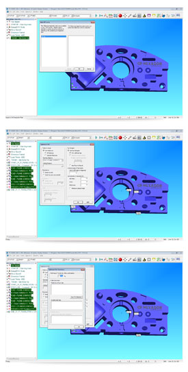
With PC-DMIS Planner tools, the measurement path can be optimized automatically. The software groups inspected features by proximity and probing angle, minimizing probe rotations and tip changes. Multiple Measurement Plan default parameters can be set by the inspector to clarify the number of points taken and their locations for various customer or internal inspection requirements. Also, once the plan is imported, the real time functionality of PC-DMIS can be utilized to either step through the measurement plan making changes on the fly, or spot-edit known areas of concern or key characteristics. Most inspection routines will see a thirty percent increase in throughput using this new approach, while others reap increases of more than fifty percent.
Since efficiency equates to speed, and speed requires safety, another software advancement takes advantage of the PC-DMIS model’s inherent bounding box. Parts that are round or irregularly shaped (for example turbine blades, steering control arms, prosthetics/implants, etc.), are contained within the bounding box as well. When this "force field" is activated in PC-DMIS, advanced algorithms will direct the probe tip to automatically clear the part. This requires the probe to safely back away from the part and fixture before moving to the next feature or completing a probe head rotation. No longer must the operator worry about moves.
MBD promises to reduce the workload of inspectors by assuming some of the grunt work associated with change revisions. Although inspectors will still need to finesse the results by applying their specialized knowledge of metrology best practices, fixturing, customer requirements, and the application of GD&T, a large percentage of the time spent adjusting inspection routines to match revisions will be eased as the software assumes that responsibility.
As more companies strike MBD gold, quality assurance departments will experience an uptick in productivity, while engineers move even closer to preserving the original design intent of their parts and assemblies. With all of this progress, it is not hard to imagine a world where quality technicians are streamlining part inspections without breaking a sweat.
MBD “gold” lies in its ability to streamline product development into a drawing-free process based on an information-rich 3D CAD model that fully defines and provides specifications for parts and assemblies. This next-generation approach to product design has several time- and money-saving ramifications from simplifying manufacturing operations to greatly improving inspection processes.
The talk of MBD inspections
The transition toward 3D CAD has accelerated in recent years as more and more design and manufacturing companies embrace solid and surface modeling techniques. However, 3D models lacked GD&T (geometric dimensioning and tolerancing) information, so it was anyone’s guess as to the part’s allowable discrepancies. Additionally, any change to the original design intent turned into a lengthy process of redesigning detailed prints – sometimes repeatedly – with each change consuming valuable time and introducing the potential for errors. All of these intricacies roll down to the desk of the quality inspector.In the quality assurance world, the main problem with the typical CAD model is that it requires a separate blueprint to determine datum structure, key characteristics, and tolerancing to create an inspection plan. This scenario occasionally requires access to the product designer to interpret some of the GD&T information, which is not exactly convenient for multinational corporations. Stir in the nagging question of whether the CAD data or the print is the most current revision, and you have a recipe for convolution.
MBD has arrived on the scene to alleviate this complexity, as several CAD software packages now allow for embedded GD&T. All pertinent product information and inspection planning data is incorporated into one version-controllable entity - the 3D CAD model. MBD consolidates component datum structure and revision levels, GD&T interpretation, product details and any other necessary dimensioning into the model. For quality assurance purposes, this is good news…very good news.
Real benefits
To get a sense of what is possible, it is worthwhile to study the inherent benefits of an information-rich CAD model. For starters, MBD provides, for the first time, a formal communications vehicle between design and quality without the need for prints, so design intent is automatically available at the time of part program creation. With CAD software tools, component manufacturers are able to receive a single CAD file and complete all the necessary steps to build and inspect a given part.Secondly, MBD solves human error issues by transferring notes into inspection software. The traditional use of 2D drawings to supply documentation such as GD&T, bill of materials and other engineering configurations has left companies exposed to the inherent risk of human error in the interpretation of this information. Model based definition solely relies on 3D digital data to define and supply specifications for parts and product assemblies, giving plausible meaning to the term “paperless inspection.”
Lastly, and most significantly, MBD delivers an automated mechanism for part program creation directly from the 3D design information. Inspection programs change as design modifications are made, and dependencies are also updated automatically. When the tolerance of one feature changes, the program updates all associated features. This capability is a valuable time saver, especially on more complex parts. For example, if a part contains 80 holes with similar tolerancing and a specification changes, a simple click will instantly update all associated dimensions without further operator intervention.
No longer just talk
In the natural scheme of progress, a few CAD-based inspection software platforms are keeping pace with MBD and capitalizing on the advantages of the new embedded GD&T data. Some systems provide the basic ability to create features, datum definitions, and associated dimensions from a single mouse click. PC-DMIS Planner, an inspection planning software developed by Hexagon Manufacturing Intelligence, takes it one step further by automating the inspection process based on design changes and embedded GD&T. The software can create full and sub-inspection programs and control revisions all while using a program that is device neutral. It can also be used regardless of the measurement technology employed, such as touch, scan, continuous analog, vision, and laser .When this inspection software is dynamically linked to CAD, its Change Manager feature notifies the quality technician of updates or changes to the CAD model. These changes can be accepted or rejected, with the software automatically revising the inspection path based on the most efficient route to incorporate the required changes. Although the inspection routine of features and dimensions is automatically generated with emphasis on measurement efficiency, the user can easily customize the measurement report to suit the desired requirements.
It is a simple process to import CAD data and select feature control frames and/or other linear dimensioning from the 3D model. Each dimension selected will add the most up-to-date features and tolerancing to the inspection plan based on the designer’s intent, eliminating interpretation by the inspector. The software uses PTB certified algorithms for ASME Y14.5 – 1994, ASME Y14.5 – 2009 and ISO standards to ensure the highest level of measurement acceptance accuracy. This is done automatically when the initial plan is created. The inspection software also ensures common datum features referenced by multiple feature control frames are not duplicated in the inspection routine, which keep inspection time efficient while maintaining accuracy. This is a paradigm shift in the process as ensuring throughput and accuracy has always been the responsibility of the quality technician. In essence, Model Based Definition shifts that burden from the technician to the software.
With PC-DMIS Planner tools, the measurement path can be optimized automatically. The software groups inspected features by proximity and probing angle, minimizing probe rotations and tip changes. Multiple Measurement Plan default parameters can be set by the inspector to clarify the number of points taken and their locations for various customer or internal inspection requirements. Also, once the plan is imported, the real time functionality of PC-DMIS can be utilized to either step through the measurement plan making changes on the fly, or spot-edit known areas of concern or key characteristics. Most inspection routines will see a thirty percent increase in throughput using this new approach, while others reap increases of more than fifty percent.
Since efficiency equates to speed, and speed requires safety, another software advancement takes advantage of the PC-DMIS model’s inherent bounding box. Parts that are round or irregularly shaped (for example turbine blades, steering control arms, prosthetics/implants, etc.), are contained within the bounding box as well. When this "force field" is activated in PC-DMIS, advanced algorithms will direct the probe tip to automatically clear the part. This requires the probe to safely back away from the part and fixture before moving to the next feature or completing a probe head rotation. No longer must the operator worry about moves.
MBD – Where do we go from here?
Using the unstoppable force of 3D information, MBD continues on a path to reach its full potential. Companies can leverage their CAD models for further improvements in the product development process, and at the same time, garner quality assurance gains through inspection software enhanced to take full advantage of MBD. By embedding all relevant information within the CAD model, an organization should expect to save time and reduce the potential for human error.MBD promises to reduce the workload of inspectors by assuming some of the grunt work associated with change revisions. Although inspectors will still need to finesse the results by applying their specialized knowledge of metrology best practices, fixturing, customer requirements, and the application of GD&T, a large percentage of the time spent adjusting inspection routines to match revisions will be eased as the software assumes that responsibility.
As more companies strike MBD gold, quality assurance departments will experience an uptick in productivity, while engineers move even closer to preserving the original design intent of their parts and assemblies. With all of this progress, it is not hard to imagine a world where quality technicians are streamlining part inspections without breaking a sweat.