How to select a CMM
The right CMM makes all the difference in measuring operations.
Contact us
Process control and quality assurance in modern manufacturing operations depend increasingly on the performance of coordinate measuring machines (CMMs). Over the past 20 years, CMMs have replaced traditional methods of inspection with gages and fixtures and have reduced the time and manpower required in quality control operations.
CMMs not only provide the capability to inspect standard geometrical dimensions, but also parts with special features such as gears, camshafts, airfoil shapes, and many others. In a traditional manufacturing environment, each of these special inspections would require a single purpose testing machine.
Product quality does not only depend on the quality of the machine tools used for manufacturing; it also depends on the accuracy and repeatability of measuring and inspection devices. A low cost, low performance machining center in combination with a high precision CMM can still guarantee product quality because only parts within the tolerance can pass the CMM's inspection. Conversely, an expensive, high quality machining center in combination with a low cost, low accuracy measuring device cannot guarantee quality products. A certain percentage of out-of-tolerance parts will always pass the low accuracy CMM inspection, and likewise, a certain percentage of parts within the tolerance range will be rejected. Consequently, the selection of the right CMM is a critical decision. The purpose of this article is to help you choose a CMM that meets your specific accuracy and application requirements.
The first important selection criterion is the determination of the minimum required measuring range of the CMM. This range usually depends on the dimensions of the part to be measured, but is often more complex than that. For example, if the configuration of the part and the inspection routine require the use of probe extensions and fixtures, the actual minimum required measuring range could be considerably larger than workpiece dimensions.
As a guideline to properly sizing your CMM, consider choosing a machine whose X, Y and Z measuring ranges are twice the width, length and height of the largest part you need to measure.
The second selection criterion is the minimum required uncertainty. The uncertainties and test procedures for CMMs are described in ISO 10360-2. Some CMM manufacturers do not conform to ISO 10360-2, but use other performance standards such as CMMA, VDI/VDE 2617, B89, and JIS (See Understanding CMM Performance Standards, page 6). However, in order to compare CMMs from different manufacturers, make sure you compare like specifications. Most CMM manufacturers already offer their specifications in a variety of formats to support their international customer base. In addition, if you're an international manufacturer, it may be prudent to request the CMM's specifications in the ISO 10360-2 format since it's becoming a world standard. This will allow you to not only compare between competitors, but to compare the new machine to your existing machines installed throughout the world.
ISO 10360-2, in force since 1994, specifies two uncertainties, volumetric length measuring uncertainty (E), and volumetric probing uncertainty (R).
To verify a CMM's volumetric length measuring uncertainty, a series of gage blocks or a step gage are used. The user selects seven different locations (position and direction) within the CMM's measuring volume for the test.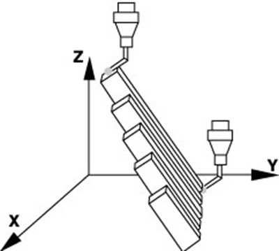
For each of the seven locations, five material standards (lengths) are measured three times each for a total of 105 measurements. All 105 measurement results, 100 percent, must be within the stated tolerance specified by the manufacturer.
A precision sphere between 10 mm and 50 mm with form and diameter certification is used to verify a CMM's probing uncertainty. The test consists of measuring 25 equally spaced points on the sphere. R is computed by adding the absolute values of the minimum and maximum deviation from the radial form. The result is reported in micrometers (µm), and all 25 probings must be used in the calculation.
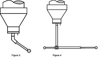
These tests are very specific both in definition and execution. It is important to remember that a CMM's uncertainty under actual operating conditions can be larger than stated on the manufacturer's specifications because of the use of probe extensions, long or slender probes, rotary tables, revolving probe heads, temperature changes, and airborne contaminants in the shop.
For example, in E and R as specified are determined by one styli fixed directly in the probe head with no extensions and no rotation. However, most workpieces require complex probe configurations for which E and R are not specified. A work-piece might require the combination of several probe pins, extensions, rotation of the probe head, and perhaps a probe change during the course of the inspection program.
Because of these differences, the generally accepted practice is to apply a ratio of uncertainty to tolerance when calculating a required CMM specification. This ratio may vary widely depending on the factors described above, the complexity of the measurement task and the process itself. Typical ratios range from 1:3 to 1:20 with 1:5 and 1:10 being the most common. In order to maintain a 1:5 ratio of uncertainty to part tolerance, the CMM data sheet specification should be five times more accurate than the tolerance being inspected.
On almost all work pieces, CMMs must inspect three groups of features-diameters and distances, position tolerances and form tolerances. An analysis of the required uncertainty must be performed for each group.
For diameter and distance tolerances, refer to the part drawing and locate the diameter for distances with the tightest tolerances. Because of the length dependency of volumetric uncertainty, a larger tolerance on a very long feature may present more difficulty than a very tight tolerance on a small feature. Figure 5 illustrates how to calculate the required machine volumetric length measurement uncertainty.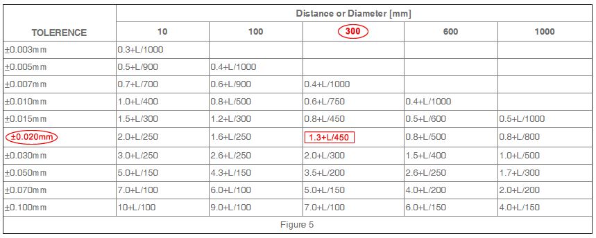
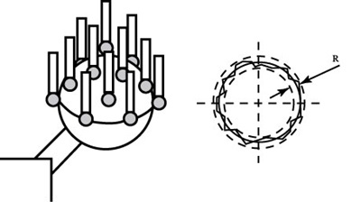
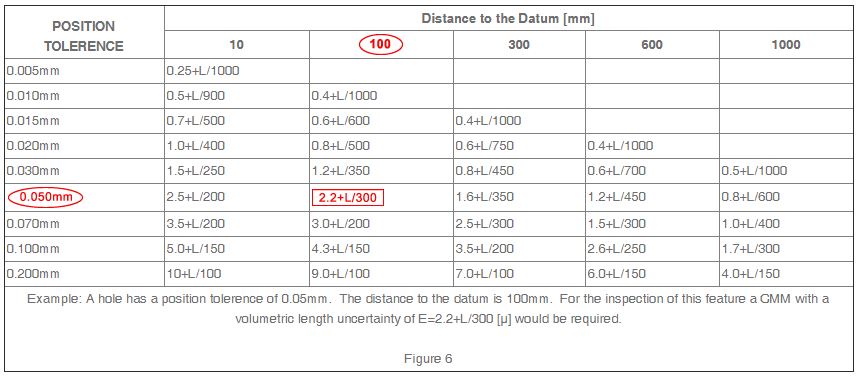
Since position tolerances usually define a tolerance diameter, only the radius is used to determine the deviation from the nominal center. Figure 6 illustrates the method used to calculate the required machine uncertainty.
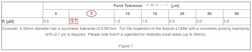
Form tolerances include call outs for roundness, flatness, straightness, cylindricity, and profile form. Figure 7 illustrates the calculation of machine measurement uncertainty for form tolerances.
The uncertainty of every CMM depends to a great extent on environmental conditions. Consequently, CMM manufacturers usually specify the temperature range, temperature variation per hour, temperature variation per day, and temperature variation per meter within which a particular CMM achieves its performance specifications. These variables must be considered when selecting an appropriate CMM.
In addition, the level of floor vibration is important to optimizing the performance of the CMM. Most manufacturers supply the maximum vibration that the machine can withstand and still meet stated specifications. Optional active and passive vibration damping systems can also be purchased that allow the machine to be installed in less-than-friendly environments and perform to the published specs. It's important to have a complete seismic vibration study performed at the preferred installation site if you think vibration is an issue.
All CMM manufacturers provide software for basic measuring routines. Some also provide software for parts with more complex geometries such as bevel gears, impellers, screw compressors, and hob cutters to name a few. Be sure you understand the complexity of the measuring routine needed to inspect your parts and select the software package that will perform the measurement tasks necessary.
Throughput requirements are also a consideration. The more parts a CMM can inspect per day, the lower the inspection cost per part. Acceleration and the number of probing points per minute are the factors that determine overall throughput. Throughput can also be increased by special fixturing arrangements, such as pallet inspection of parts.
Selecting the CMM most appropriate for your application requires some thought and research, but you don't have to do it alone. CMM manufacturers like Hexagon Metrology have specialists who will work with you to help you choose the CMM the best fits your requirements.
CMMs not only provide the capability to inspect standard geometrical dimensions, but also parts with special features such as gears, camshafts, airfoil shapes, and many others. In a traditional manufacturing environment, each of these special inspections would require a single purpose testing machine.
Product quality does not only depend on the quality of the machine tools used for manufacturing; it also depends on the accuracy and repeatability of measuring and inspection devices. A low cost, low performance machining center in combination with a high precision CMM can still guarantee product quality because only parts within the tolerance can pass the CMM's inspection. Conversely, an expensive, high quality machining center in combination with a low cost, low accuracy measuring device cannot guarantee quality products. A certain percentage of out-of-tolerance parts will always pass the low accuracy CMM inspection, and likewise, a certain percentage of parts within the tolerance range will be rejected. Consequently, the selection of the right CMM is a critical decision. The purpose of this article is to help you choose a CMM that meets your specific accuracy and application requirements.
The first important selection criterion is the determination of the minimum required measuring range of the CMM. This range usually depends on the dimensions of the part to be measured, but is often more complex than that. For example, if the configuration of the part and the inspection routine require the use of probe extensions and fixtures, the actual minimum required measuring range could be considerably larger than workpiece dimensions.
As a guideline to properly sizing your CMM, consider choosing a machine whose X, Y and Z measuring ranges are twice the width, length and height of the largest part you need to measure.
The second selection criterion is the minimum required uncertainty. The uncertainties and test procedures for CMMs are described in ISO 10360-2. Some CMM manufacturers do not conform to ISO 10360-2, but use other performance standards such as CMMA, VDI/VDE 2617, B89, and JIS (See Understanding CMM Performance Standards, page 6). However, in order to compare CMMs from different manufacturers, make sure you compare like specifications. Most CMM manufacturers already offer their specifications in a variety of formats to support their international customer base. In addition, if you're an international manufacturer, it may be prudent to request the CMM's specifications in the ISO 10360-2 format since it's becoming a world standard. This will allow you to not only compare between competitors, but to compare the new machine to your existing machines installed throughout the world.
ISO 10360-2, in force since 1994, specifies two uncertainties, volumetric length measuring uncertainty (E), and volumetric probing uncertainty (R).
To verify a CMM's volumetric length measuring uncertainty, a series of gage blocks or a step gage are used. The user selects seven different locations (position and direction) within the CMM's measuring volume for the test.
For each of the seven locations, five material standards (lengths) are measured three times each for a total of 105 measurements. All 105 measurement results, 100 percent, must be within the stated tolerance specified by the manufacturer.
A precision sphere between 10 mm and 50 mm with form and diameter certification is used to verify a CMM's probing uncertainty. The test consists of measuring 25 equally spaced points on the sphere. R is computed by adding the absolute values of the minimum and maximum deviation from the radial form. The result is reported in micrometers (µm), and all 25 probings must be used in the calculation.
These tests are very specific both in definition and execution. It is important to remember that a CMM's uncertainty under actual operating conditions can be larger than stated on the manufacturer's specifications because of the use of probe extensions, long or slender probes, rotary tables, revolving probe heads, temperature changes, and airborne contaminants in the shop.
For example, in E and R as specified are determined by one styli fixed directly in the probe head with no extensions and no rotation. However, most workpieces require complex probe configurations for which E and R are not specified. A work-piece might require the combination of several probe pins, extensions, rotation of the probe head, and perhaps a probe change during the course of the inspection program.
Because of these differences, the generally accepted practice is to apply a ratio of uncertainty to tolerance when calculating a required CMM specification. This ratio may vary widely depending on the factors described above, the complexity of the measurement task and the process itself. Typical ratios range from 1:3 to 1:20 with 1:5 and 1:10 being the most common. In order to maintain a 1:5 ratio of uncertainty to part tolerance, the CMM data sheet specification should be five times more accurate than the tolerance being inspected.
On almost all work pieces, CMMs must inspect three groups of features-diameters and distances, position tolerances and form tolerances. An analysis of the required uncertainty must be performed for each group.
For diameter and distance tolerances, refer to the part drawing and locate the diameter for distances with the tightest tolerances. Because of the length dependency of volumetric uncertainty, a larger tolerance on a very long feature may present more difficulty than a very tight tolerance on a small feature. Figure 5 illustrates how to calculate the required machine volumetric length measurement uncertainty.
Since position tolerances usually define a tolerance diameter, only the radius is used to determine the deviation from the nominal center. Figure 6 illustrates the method used to calculate the required machine uncertainty.
Form tolerances include call outs for roundness, flatness, straightness, cylindricity, and profile form. Figure 7 illustrates the calculation of machine measurement uncertainty for form tolerances.
The uncertainty of every CMM depends to a great extent on environmental conditions. Consequently, CMM manufacturers usually specify the temperature range, temperature variation per hour, temperature variation per day, and temperature variation per meter within which a particular CMM achieves its performance specifications. These variables must be considered when selecting an appropriate CMM.
In addition, the level of floor vibration is important to optimizing the performance of the CMM. Most manufacturers supply the maximum vibration that the machine can withstand and still meet stated specifications. Optional active and passive vibration damping systems can also be purchased that allow the machine to be installed in less-than-friendly environments and perform to the published specs. It's important to have a complete seismic vibration study performed at the preferred installation site if you think vibration is an issue.
All CMM manufacturers provide software for basic measuring routines. Some also provide software for parts with more complex geometries such as bevel gears, impellers, screw compressors, and hob cutters to name a few. Be sure you understand the complexity of the measuring routine needed to inspect your parts and select the software package that will perform the measurement tasks necessary.
Throughput requirements are also a consideration. The more parts a CMM can inspect per day, the lower the inspection cost per part. Acceleration and the number of probing points per minute are the factors that determine overall throughput. Throughput can also be increased by special fixturing arrangements, such as pallet inspection of parts.
Selecting the CMM most appropriate for your application requires some thought and research, but you don't have to do it alone. CMM manufacturers like Hexagon Metrology have specialists who will work with you to help you choose the CMM the best fits your requirements.