Should you scan it?
Industrial metrology professionals are constantly tasked with finding the best methodology to inspect parts.
Contact us
Industrial metrology professionals are constantly tasked with finding the best methodology to inspect parts. When researching coordinate measuring machines (CMMs), or evaluating the capabilities of existing equipment, the discussion naturally turns toward accessories which will complement the CMM. Several solutions exist – each with its associated benefits and drawbacks. The trick is finding the correct option that is neither overkill nor inadequate.
When measuring small- to medium-sized parts, there are four main categories of inspection accessories available. The first are touch-trigger probes which take discrete points on a part. The second is analog scanning probes which run along the surface of a part, taking thousands of individual points at a time. 3D Laser scanners use a laser stripe to take thousands, or even millions, of points on a surface. Finally, chromatic white light sensors (CWS) offer high-accuracy non-contact inspection.
When faced with the decision of whether to scan a part, metrology professionals inherently lean toward analog scanning as it captures a large amount of high-accuracy 3D coordinate data with easy access to most areas. It is also ideal because it is more likely that all critical features are captured. Using analog scanning improves repeatability of the results while decreasing measurement uncertainty. In reality, however, the decision to scan a part is more nuanced and dependent on the application.
What could go wrong?
The first step in evaluating inspection techniques is to look at the overall manufacturing process and think about what could potentially go wrong. For example, if the part is a plastic component is there a thicker area prone to sinkage as the material cools and settles? If the answer is yes, and it is a critical feature with high tolerances, it should be scanned. If the feature is not critical and has low tolerances, touch probing is likely sufficient.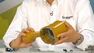 Also, when evaluating the process, the component’s use should be taken into consideration. A plastic connector for automotive parts, such as the one shown above requires a tight seal to eliminate the possibility of water ingress. Though the connector has simplistic features that could easily be touch probed, the edge where it forms a seal will likely have tighter tolerances that require analog scanning.
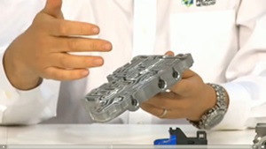
Die-cast aluminum nail gun housing A skilled metrology professional will review the manufacturing process from start to finish to determine the best approach. A nail gun that has some interesting features on the original die-cast component is shown here. Additionally, there are machining processes that factor into the decision of whether or not to scan. On this particular component, the company may check its profile by 3D laser scanning the die-cast aluminum housing. When checking other features, especially those located beneath the surface of the part, analog scanning or even touch probing would be adequate. Another feature to check would be mating surfaces of the component. Since there could be an issue of fit, analog scanning might be a better choice on such surfaces.
What are the tolerances?
As alluded to previously, the tolerance required on a given datum will play into determining the ideal inspection method. Although laser scanning has come a long way since its inception, it is still relatively poor in terms of accuracy when compared with other methods. Laser scanning should not be used when tolerances are tighter than ± 0.01”, but is ideal for looser tolerances on parts with numerous surfaces controlled by profile. Touch probing delivers higher accuracy, but it has a lower repeatability when compared with analog scanning probes. Analog scanning is considered the most accurate method of inspecting a part and can hold tolerances of up to ± 0.0005”. Chromatic White Light sensors (CWS) are high-accuracy non-contact method of inspection that has the capability of measuring down to 10 nanometers. CWS are used for features too small to measure with a touch probe, or for components that require non-contact measurement such as flexible parts.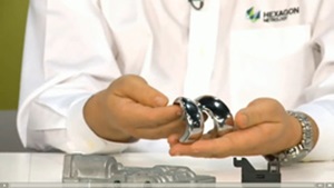 In the case of certain medical components, for example the femoral shown here, analog scanning will be the ideal option. This is because the profile needs to be inspected to a high level of accuracy. In some instances, non-contact scanning through a CWS is preferable if the part cannot be touched. A CWS is also ideal for highly reflective, transparent and matte black surfaces.
On the other end of the spectrum, certain parts lend themselves to discrete point probing. A stamped component with loose tolerances, where form is not an issue and the profile of hole locations is required, is best suited for point probing. Even though the part may contain multiple features, scanning is overkill and a waste of time and money.
Some parts could have a several callouts with a large variety of tolerances. In this instance a multisensor CMM would be the ideal choice since parts could be measured with different sensors within the same program. For example, on the die-cast top plate of an automatic transmission seen below, there are machined features with generally toleranced holes, but internally there are high-accuracy features. Because of the variety of features on the part, the initial casting might be laser scanned when it is received from the supplier. After machining, analog scanning the face is recommended because there is likely to be tight tolerance form callouts so it can form a seal with the transmission. The bore holes might also be scanned or, depending on their tolerances, touch probed to save time.
Paintbrush or pen?
 When evaluating the proper inspection method for components, the desired throughput should be taken into account. There are three main categories. Single point, usually done with touch probes, takes one measurement at a time but is fairly slow at approximately one point a second. Analog probing gathers a single line of data similar to a pen creating a single line. Sensors that fall into this category are analog scanning probes and the CWS. For high data collection, the 3D laser stripe sensor offers high point density as it is more comparable to paintbrush.
Collecting data quickly and accurately is a great capability, but there are no benefits unless it is presented in an understandable way to the intended audience. Today, the trend is to employ laser scanning because it is fast, fairly accurate and all required datums are captured at once. However, this capability may not be necessary for collecting the data needed to inspect critical features.
Once data is gathered, the question of data management surfaces, or what should be done with the information. Is the goal to simply compare the physical part to its CAD model and, if so, what are the main areas of concern? Millions of data points can be collected with a laser sensor. If the plan for that data is to see how the part looks, the company has lost sight of its true purpose of verifying the critical features of the part. In many cases, an excessive amount of point data can be a detriment instead of a benefit—bogging down software and computing processes or focusing unnecessary attention on non-critical areas.